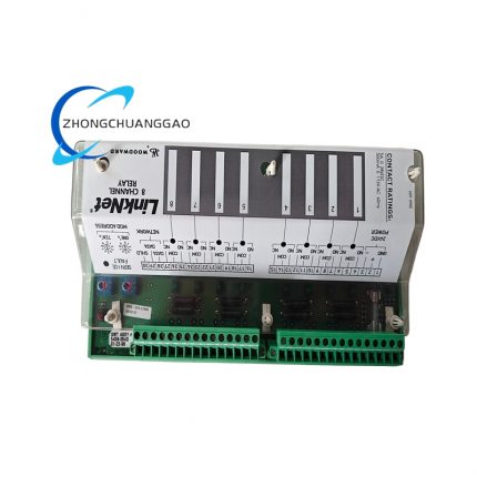
Product Introduction
- This is analog-circuit-based dedicated generator synchronization controller belonging to Woodward SPM-A standardized product series, exclusively designed for frequency and phase closed-loop matching between standalone generator set and utility bus or another running generator before grid paralleling operation.
- The device collects real-time AC voltage sampling signals from on-site generator terminal and public power bus terminal, calculates frequency deviation and phase angle difference via internal analog operational amplifier circuit, outputs proportional corrective bias signal to matched Woodward speed governor to adjust prime mover rotating speed automatically.
- The unit automatically triggers external circuit breaker closing signal only when actual phase deviation falls within preset safety window, completely avoids surge current and mechanical impact damage caused by out-of-phase paralleling of generator sets; this model cancels built-in automatic voltage matching function, needs external independent AVR device to complete generator voltage regulation task.
- The whole product passes CE industrial safety certification and IEC61000 EMC anti-interference certification, supports continuous 24-hour uninterrupted fixed installation inside power control cabinet of generator room, marine cabin and outdoor standby power station equipment room.
3. Model Series Information
- Parent Affiliated Product Series: Woodward SPM-A Full Analog Synchronizer Series (9907 serial coding rule)
- Core peer derivative models under SPM-A product line:
- 9907-029: SPM-A synchronizer with built-in full automatic voltage matching function
- 9907-030: Wide-frequency-range 45~65Hz customized SPM-A marine special synchronizer
- 9907-031: Low-voltage 120VAC input version SPM-A for small-size diesel generator
- All SPM-A series models keep unified external installation dimension and terminal definition standard, only differ in internal voltage matching circuit and parameter preset range.
4. Technical Specifications
4.1 AC Sampling Input Specification
- Rated Generator & Bus Sampling Input Voltage: 115VAC / 230VAC RMS dual selectable, input voltage allowable fluctuation tolerance: ±10% rated value
- Standard applicable grid frequency: 50Hz & 60Hz dual universal compatible, intrinsic effective frequency tracking range: 47Hz~63Hz
- Rated preset safety closing phase window: ±10° nominal phase difference, adjustable range via internal precision potentiometer from ±3° to ±15°
4.2 Power Consumption Parameter
- Maximum total static power consumption under full operating status: ≤5W at rated input voltage condition
4.3 Control Output Specification
- Three standard independent signal output terminals defined by factory specification:
- High Impedance Output Terminal Group: Matches Woodward 2301 standard load sharing governor system
- Low Impedance Output Terminal Group: Matches 2301A, 2500, EPG series Woodward speed control equipment
- Dedicated EPG Special Output Terminal: Exclusive for Woodward EPG speed controller without load detection function
- Field configurable breaker dwell matching time (closing delay): Fixed four optional grades: 1/8s, 1/4s, 1/2s, 1s; factory default fixed setting: 1/2 second
4.4 Physical & Environmental Specification
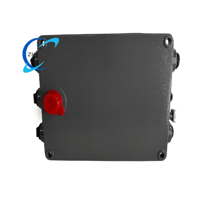
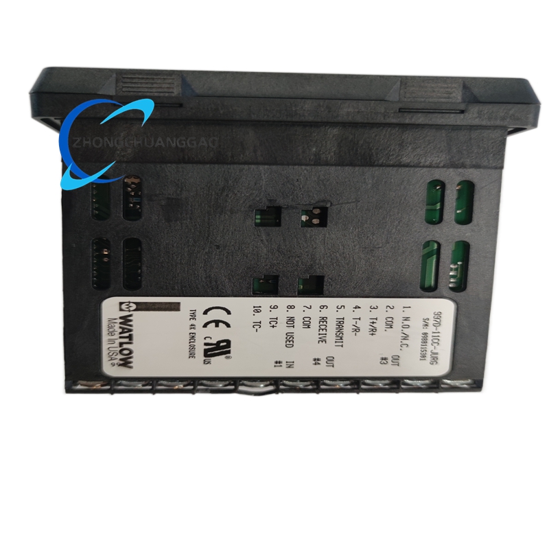
- Overall outer dimension: 273.6mm(D) × 214.1mm(W) × 59.2mm(H)
- Standard single unit net weight: 1.71kg
- Certified continuous long-term operating ambient temperature range: -45℃ ~ +70℃; optimal stable working ambient range: +10℃ ~ +30℃
- Storage & transportation allowable temperature range: -50℃ ~ +85℃; permitted operating relative humidity: 5%~95%RH non-condensing environment only
- Cabinet casing protection grade: IP20; exposed wiring terminal region protection grade: IP00
5. Function Features
- Independent dual-channel AC signal sampling circuit for generator side and bus side separately, built-in transient overvoltage absorption circuit to suppress instantaneous lightning surge interference from field input wiring.
- Multi-grade adjustable synchronization dynamic response characteristic via front panel potentiometer setup, adapts different inertia parameters of diesel engine, gas engine prime mover unit.
- Selectable four-grade closing dwell time setting, matches different mechanical closing response speed of various specification AC circuit breakers on-site.
- Three-type standard analog bias output design realizes seamless docking with full mainstream Woodward series mechanical and electronic speed governors without extra signal conversion accessory.
- Fixed interlock logic design prohibits circuit breaker closing signal output when phase difference exceeds preset safety window, fundamentally prevents out-of-phase grid connection fault.
- Front panel status indicator lamp layout: Green LED for normal sampling power-on status, Red LED for out-of-phase deviation over-limit warning.
- Full analog hardware circuit structure without embedded program firmware, no software crash or parameter loss failure risk caused by program breakdown.
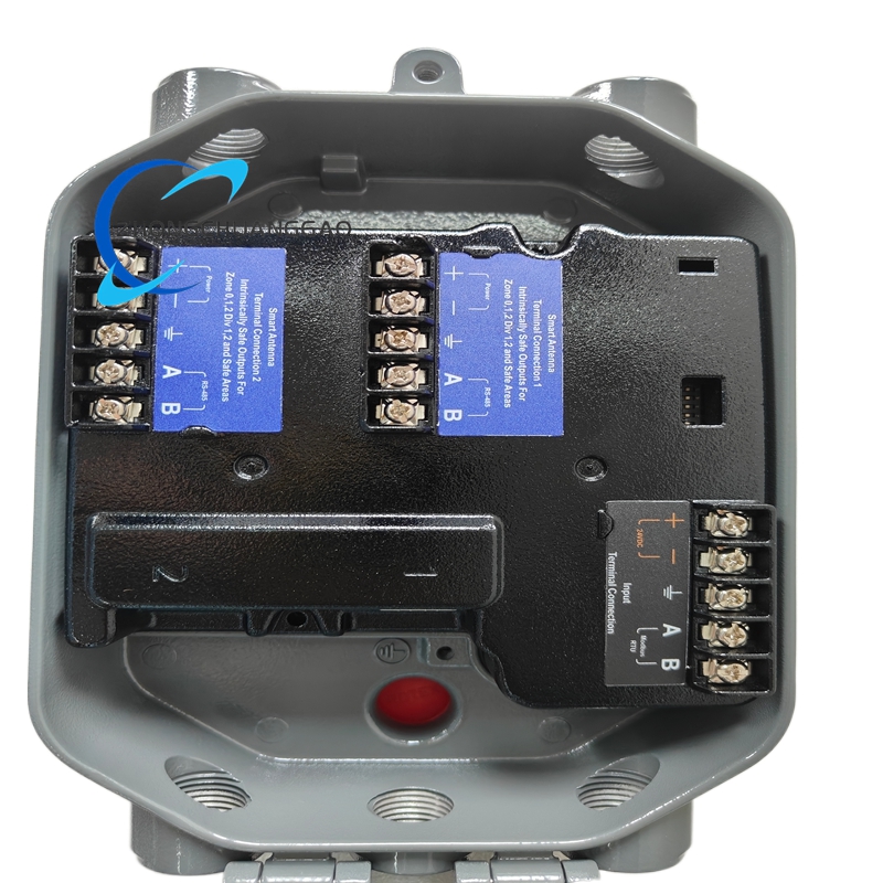
- Terminal wiring area adopts partition layout to isolate AC sampling input terminals and DC control output terminals for anti-cross-interference protection.
6. Performance Parameters
- Nominal phase detection resolution: ≤0.2° phase angle discrimination accuracy under rated 50/60Hz input condition
- Frequency tracking response speed: Completes full frequency deviation capture within 3 cycles of AC input waveform
- Rated MTBF value under certified working temperature range: ≥280000 continuous running hours
- Input common-mode interference rejection ratio: ≥125dB at industrial standard 50Hz power frequency
- Allowable maximum input instantaneous surge voltage: 2.5kVAC transient impulse without internal circuit damage
- Output bias signal linearity error: ≤±0.3%FS within full frequency deviation adjustment range
7. Material Composition
- Outer equipment cabinet housing: 1.2mm thickness cold-rolled SPCC steel plate with matte black electrostatic anti-corrosion spray coating, coating meets UL94-V0 flame retardant fire protection standard.
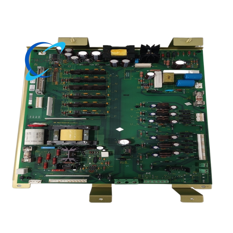
- Internal main PCB substrate: High-Tg FR-4 industrial glass fiber printed circuit board, whole board surface coated with three-proof acrylic conformal coating for moisture-proof, sulfur-proof and mildew-proof protection.
- Core analog processing components: Military-grade wide-temperature operational amplifier chips, high-precision metal film trimming potentiometers for parameter adjustment.
- Passive electronic components: High-temperature solid tantalum capacitors, metal film fixed resistors rated -45℃~+125℃ working temperature range.
- External wiring terminal base: Glass fiber reinforced PA66 flame retardant nylon terminal block with silver-plated copper alloy spring conductive shrapnel, terminal function identification marked via permanent laser engraving process.
- Indicator light accessory: Industrial-grade long-life LED indicator components with anti-aging epoxy encapsulation structure.
8. Structural Characteristics
- Integral rectangular closed metal casing overall forming structure, front panel centralized arrangement of parameter adjustment potentiometers and status indicator LEDs, rear panel full-row fixed wiring terminal strip layout.
- Internal three-layer space partitioning layout: Front indicator and adjusting component layer, middle analog signal processing PCB layer, rear terminal wiring isolation layer.
- PCB board separates analog sampling ground and control signal ground via independent wiring routing to eliminate internal circuit crosstalk interference.
- Reserved natural convection heat dissipation gap between internal PCB and outer metal casing for passive heat dissipation during long-term continuous full-load operation.
- Two symmetrical reserved mounting fixing holes on left and right side of casing for screw fixed installation inside switchgear cabinet or standard control panel.
- Plastic isolation ribs between different function terminal areas on rear terminal base to avoid accidental short-circuit caused by wiring misoperation.
9. Working Principle
- AC Sampling Input Stage: Generator terminal AC voltage and public grid bus AC voltage transmit to corresponding two groups of input terminals, signals pass through built-in surge absorption and impedance matching circuit before sending to analog phase comparison core circuit.
- Phase & Frequency Calculation Stage: Internal analog comparison circuit real-time identifies frequency difference and phase angle offset between two groups of AC waveforms, converts deviation value into proportional continuous analog DC bias voltage signal.
- Governor Bias Output Stage: Generated DC bias signal is selectively output via high/low impedance/EPG three optional output channels to matched Woodward speed governor; governor receives bias signal to adjust fuel supply of prime mover and change generator rotating speed automatically for frequency and phase convergence.
- Closing Logic Judgment Stage: When real-time detected phase difference reduces within preset ±10° safety window, internal relay contact closes and outputs valid closing control signal to drive external AC circuit breaker action to finish generator grid paralleling.
- Status Indication Stage: Internal circuit drives front panel LED indicators according to real-time working state; green light keeps steady on under normal sampling condition, red light lights up when phase deviation exceeds preset threshold value.
10. Advantage Highlights
- Pure analog hardware control architecture eliminates hidden troubles of digital controller firmware failure, code crash and parameter lost, adapts severe high-low temperature and strong electromagnetic interference industrial field environment.
- Three standardized output modes realize direct matching with full mainstream Woodward governor series, no additional signal conversion module needed to reduce on-site spare part configuration cost.
- Multiple adjustable synchronization dynamic and closing delay parameters realize customized synchronization response matching for different type prime mover equipment.
- Compact metal cabinet structure saves cabinet installation space, fixed hole design supports flexible panel embedded or cabinet bottom plate dual installation modes.
- Ultra-low ≤5W power consumption design reduces cabinet internal heat accumulation, satisfies closed dense cabinet long-time uninterrupted running requirement.
- Independent overvoltage protection on input terminals prevents equipment burnout caused by field wrong high-voltage access misoperation.
- CE certified safety and EMC performance meets global power equipment access standard for domestic and overseas generator station projects.
11. Applicable Industries
- Standby Power Plant Industry: Diesel/gas emergency backup generator set automatic grid parallel synchronization control for hospital, data center and commercial complex self-contained power station.
- Marine Power Industry: Ship auxiliary diesel generator set synchronization for onboard microgrid parallel operation on cargo ship, engineering vessel and offshore platform.
- Petrochemical Industry: Refinery on-site standby gas generator set synchronization for factory self-provided power grid switching operation.
- Waste-to-Energy Power Generation Industry: Waste incineration auxiliary backup diesel generator synchronization for factory off-grid emergency power supply switching.
- Mining Industry: Underground mine standby generator set phase synchronization for mine self-contained power grid switching during municipal power outage.
- Industrial Microgrid Industry: Factory distributed gas engine generator cluster parallel synchronization for independent industrial park microgrid system.
12. Installation Requirements
- Cabinet Environment Installation Standard: Fix module inside closed well-ventilated industrial control cabinet; prohibit installation position adjacent to high heat components such as power transformer, braking resistor and thyristor power unit; surrounding ambient temperature must maintain within -45℃~+70℃ operating range.
- Mechanical Mounting Specification: Fix equipment via side reserved mounting holes with M4 standard screw onto cabinet metal backboard; reserve minimum 18mm upper and lower gap between adjacent control modules for heat dissipation air circulation.
- Field AC Sampling Wiring Rule: Generator and bus input AC signal cable uses shielded twisted pair copper wire with conductor cross-section ≥0.75mm²; shielding layer single-point grounding only at cabinet terminal side, equipment field side shielding end keeps suspended open circuit.
- Control Output Wiring Standard: Governor bias output wiring adopts shielded control cable with cross-section ≥0.5mm², separate routing from high-current power cable to avoid electromagnetic coupling interference.
- Hazardous Area Installation Specification: For Zone2 hazardous classified cabinet installation, all external field AC sampling wiring must pass certified explosion-proof junction box before connecting module terminals; direct installation inside Zone0/Zone1 explosive hazardous area is prohibited.
13. Use Precautions
- Pre-power-on Inspection Regulation: Confirm input AC voltage falls within 115VAC/230VAC ±10% rated scope before switching on equipment power supply; forbid direct access of 380VAC industrial mains voltage into sampling input terminals to avoid instant internal component burnout.
- Parameter Adjustment Specification: Complete phase window, synchronization dynamic and dwell time potentiometer setting under full power-off state; parameter modification during powered running will take effect only after equipment power cycle restart.
- Calibration Operation Condition: Finish full functional accuracy calibration under stable ambient temperature +25℃±2℃; calibration operation under ultra-high/low temperature environment is forbidden to guarantee synchronization precision.
- Maintenance Operation Rule: Cut off all external input AC power supply completely before disassembly maintenance; forbid live plugging/unplugging of field input and output wiring during powered operating status.
- Spare Module Storage Standard: Uninstalled spare products store inside constant-temperature dry warehouse with ambient humidity below 95% non-condensing; long-term storage in corrosive gas, salt fog and high-humidity closed space is permanently prohibited.
- Modification Restriction: Prohibit disassembly of sealed internal circuit components and arbitrary replacement of non-original spare parts; private circuit modification will void official product certification and equipment warranty.
- Daily Cleaning Specification: Only dry anti-static lint-free cloth is allowed to wipe front panel potentiometer and indicator surface dust; direct cleaning of PCB internal components with liquid solvent is forbidden.
- Matching Restriction: This 9907-028 model has no built-in voltage matching function; forbid using this unit alone for generator parallel system requiring automatic voltage synchronization, must configure independent external AVR voltage regulator device.


")
")


-1-430x430.jpg)


Reviews
There are no reviews yet.