3. Technical Specifications
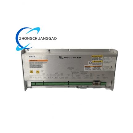
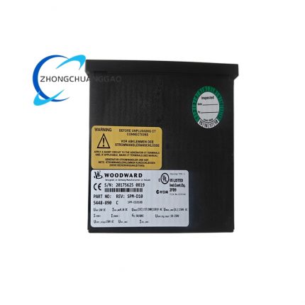
- Official Part Number: 8290-194, standard revision version E/D
- Rated Operating Power Supply: 24 VDC nominal input, allowable input range 20VDC ~ 32VDC, maximum total power consumption 95W
- Magnetic Pickup (MPU) Speed Input: Minimum effective input amplitude 1.5 VRMS AC, valid input frequency scope 3000 Hz ~ 6000 Hz
- External Analog Setpoint Input: Dual standard analog input options: 4~20mADC current signal, 1~5VDC voltage signal for remote speed setpoint adjustment
- Built-in Working Mode Selection: Isochronous zero-droop mode + adjustable droop mode (0%~8% droop coefficient full continuous regulation)
- Startup Fuel Limit Configuration: Fixed embedded start fuel limiting circuit with adjustable maximum startup fuel output upper threshold
- Dual Dynamic Control Parameter: Independent fast/slow dynamic response parameter calibration potentiometer onboard for acceleration/deceleration characteristic tuning
- Continuous Operating Ambient Temperature: -40℃ ~ +75℃, certified long-term storage temperature range: -45℃ ~ +85℃
- Valid Working Humidity Index: 5%~93% non-condensing relative ambient humidity
- Overall Physical Dimension: Width 127mm × Height 182mm × Depth 62mm; single unit net weight 2950g
- Internal Protection Fuse Specification: Built-in 10A slow-blow glass fuse for power input overcurrent protection
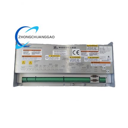
- Terminal Quantity: 12-position integrated screw-type wiring terminal block on front panel for all external signal and power wiring access
4. Functional Characteristics
- Dual dynamic independent adjustment circuit realizes separated acceleration response and deceleration response parameter setting, matches variable inertia prime mover mechanical characteristics for optimized transient speed stability.
- Integrated start fuel limiting function restricts maximum fuel supply volume during engine cold startup to avoid over-fuel black smoke emission and abnormal startup over-speed fault.
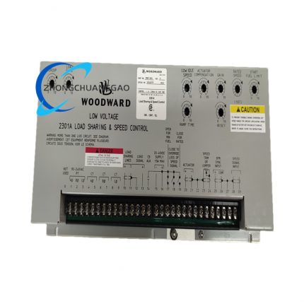
- Two fixed governing working modes switchable via onboard dial selector: isochronous constant-speed mode for single-set genset unit; adjustable droop mode for multi-unit grid parallel load sharing operation.
- Onboard multi-turn precision potentiometers realize manual rated speed fine trimming, droop ratio setting, dynamic gain modification and startup fuel limit threshold calibration without external auxiliary equipment.
- Built-in input signal filter network eliminates mechanical vibration induced high-frequency clutter noise from magnetic pickup raw AC speed signal to avoid abnormal output fluctuation.
- Standard analog remote setpoint access supports upper PLC/DCS system remote automatic speed modification via 4~20mA or 1~5VDC external control signal.
- Internal power reverse connection protection circuit prevents permanent component damage under accidental positive-negative polarity reversal of 24VDC input power supply.
5. Performance Parameters
- Steady-state speed governing accuracy under rated operating condition: ≤±0.2%FS of full rated engine speed range at 25℃ standard ambient temperature
- Transient speed deviation during full-load sudden load dump: ≤±4.2% rated speed, speed recovery stabilization time ≤380ms
- Long-term continuous powered zero drift value: ≤0.06%FS per 240 hours uninterrupted running under constant temperature environment
- Channel signal anti-crosstalk performance: No measurable output offset under simultaneous full-range variation of remote setpoint and pickup speed input
- Certified rated MTBF service life: Minimum 285000 operating hours under normal rated industrial working environment
- Vibration resistance specification: Pass 10Hz~150Hz 5g random vibration durability test without internal component desoldering and parameter drift
- EMC anti-interference index: No governing parameter deviation under 10V/m radiated RF electromagnetic field complying with IEC61000-6-2 industrial standard
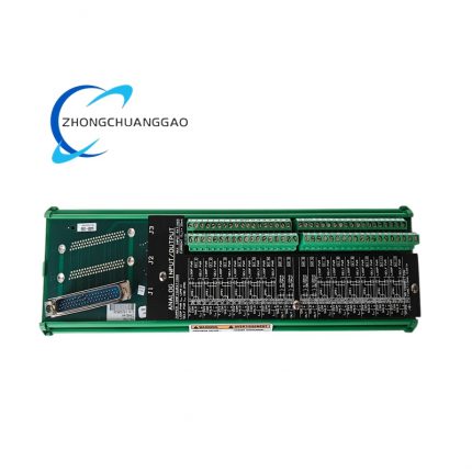
- Actuator drive output load tolerance: Stable driving output for Woodward standard EPG series electric actuator with coil resistance ranging from 3Ω to 22Ω
6. Material Composition
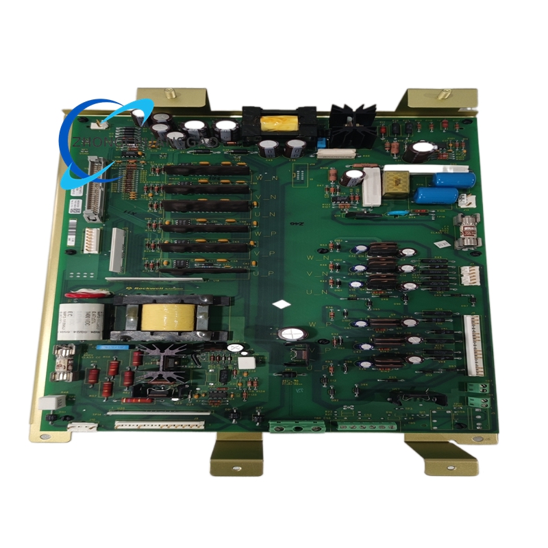
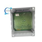
- Internal Core Circuit Substrate: High-Tg FR4 grade flame retardant epoxy glass fiber copper clad PCB with UL94-V0 fireproof certification standard
- Precision Electronic Components: Military-grade low-temperature drift metal film fixed resistors, NPO temperature-stable chip capacitors, sealed epoxy packaged operational amplifier IC and power driving triode components
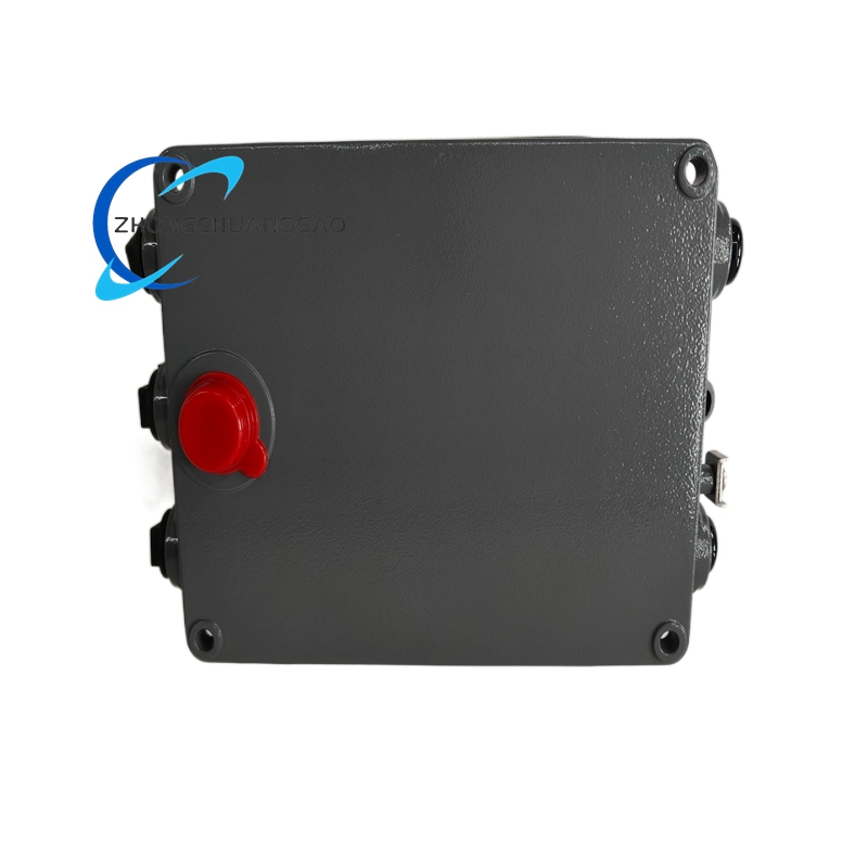
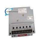
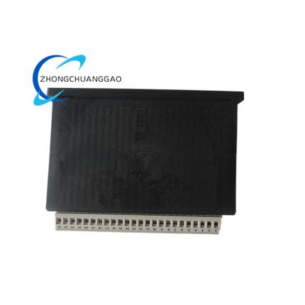
- Outer Protective Enclosure: Cold-rolled carbon steel plate after electrostatic matte black anti-rust paint spraying, shell wall thickness 1.8mm for mechanical impact resistance
- Front Wiring Terminal Block: PA66 flame retardant plastic base + nickel-plated oxygen-free copper terminal posts with anti-loose wire locking structure
- Onboard Calibration Components: Stainless steel spindle multi-turn wirewound precision trimming potentiometers with wear-resistant carbon resistance core
- Internal Fixed Fasteners: SUS304 stainless steel anti-corrosion miniature screws for PCB and internal component fixed assembly
- Insulation Isolation Parts: Polyimide high-withstand voltage insulation spacer between power circuit and weak-current signal circuit inside housing
7. Structural Features
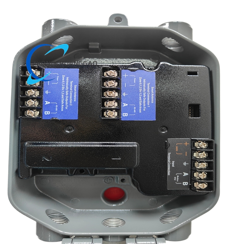
- Integral split inner structure divided into three independent functional zoning: front terminal wiring area, middle analog signal conditioning PCB area, rear power drive output area inside metal enclosure
- All calibration adjustment potentiometers uniformly arranged on upper front panel for on-site manual parameter tuning without shell disassembly operation
- 12-position sequential numbered screw terminals centralized on lower front panel, surface printed silkscreen marks each terminal definition for field wiring identification
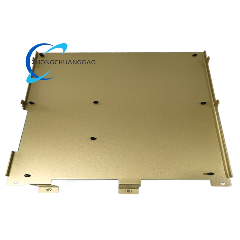
- Four-corner reserved through-hole mounting fixing holes on enclosure flange for wall-mounted or cabinet DIN fixed bracket installation
- Multiple strip-type natural heat dissipation ventilation slots symmetrically distributed on left and right side shell wall for internal heating component air convection cooling
- Internal PCB fixed with elastic shock-absorbing rubber cushion to reduce external mechanical vibration transmitted to core circuit components
8. Working Principle
Engine-mounted magnetic pickup sensor generates alternating AC sine signal whose frequency is linearly proportional to real-time prime mover rotational speed and transmits signal to controller pickup input terminal. Onboard RC low-pass filter circuit removes mechanical vibration interference clutter from raw AC signal; post-stage multi-stage amplifier circuit shapes effective speed signal into standardized frequency voltage value. Internal benchmark circuit compares actual converted speed voltage with preset rated speed reference voltage set by front panel speed trim potentiometer to generate speed deviation differential signal. Dual dynamic adjustment circuit modifies differential signal gain according to preset acceleration/deceleration parameters, processed signal is amplified by power drive circuit and converted into variable DC output voltage to drive matched fuel actuator. Actuator pushes engine fuel rack to increase or decrease fuel supply quantity to eliminate speed deviation and realize closed-loop constant speed control; startup fuel limiting circuit locks maximum output voltage value during engine startup phase to cap upper fuel supply limit, droop circuit automatically adjusts speed setpoint under load fluctuation for multi-unit parallel load sharing control.
9. Advantage Highlights
- Original Woodward factory pre-calibrated finished controller with complete production test data traceability, direct drop-in interchangeable replacement with same-series EPG controller without full recalibration after field installation.
- Unique dual-dynamic independent parameter design separately optimizes engine accelerate and decelerate governing performance to reduce transient speed fluctuation during load abrupt change.
- Built-in startup fuel limiting function eliminates engine startup over-fuel fault and optimizes cold start combustion efficiency to lower exhaust pollutant emission.
- Dual remote analog setpoint input mode realizes flexible on-site local/manual + upper system automatic dual speed control switching to match diversified automation control scheme.
- Robust full-metal sealed enclosure adapts marine engine cabin, outdoor power station, petrochemical plant harsh high-low temperature and high-humidity working environment.
- Global CE, DNV marine certification supports cross-region deployment of shipboard, offshore platform and onshore power generation international engineering projects.
10. Applicable Industries
- Marine Shipbuilding Industry: Merchant ship auxiliary diesel genset, ship emergency standby engine closed-loop speed regulation system
- Offshore Oil & Gas Industry: Offshore drilling platform diesel-driven generator and compressor unit governing control cabinet core component
- Petrochemical Refining Industry: Refinery emergency standby diesel/gas generator automatic speed control equipment
- Distributed Power Generation Industry: Small and medium-sized gas-fired diesel power plant genset speed governing system
- Mining Industrial Equipment Industry: Large fixed diesel-driven air compressor and water pump unit constant-speed control system
- Railway Auxiliary Power Industry: Locomotive auxiliary diesel generating set cabinet spare control module matching
11. Applicable Model Series
- Same EPG Product Line Peer Models: Woodward 8290-202, 8290-215, 8290-216 EPG series 24VDC engine speed controllers
- Matching Executing Component: Woodward 1712/1724/524 series EPG electric fuel actuator for fuel rack adjustment
- Matching Sensing Component: Woodward standard magnetic pickup speed sensor (MPU) with 2-wire AC signal output
- Matching Auxiliary Accessories: 24VDC stabilized switching power supply unit, double-layer shielded twisted signal cable, fixed controller mounting metal bracket
12. Installation Requirements
- Complete fixed installation operation under full power-off state of prime mover and matched control cabinet, reserve minimum 35mm upper and bottom ventilation clearance for controller natural heat dissipation after mounting.
- Fix controller via four-corner flange mounting holes with SUS304 bolts, screw tightening torque controlled at 0.9N·m to prevent long-term running vibration-induced loose installation.
- Strictly follow front panel terminal silkscreen definition for wiring: magnetic pickup signal cable adopts double-shielded twisted wire, separate weak-current signal wiring from 220VAC high-voltage power cable with minimum 15cm wiring gap to avoid power frequency interference.
- Select 12AWG~14AWG specification copper wire for 24VDC main power input wiring per cable length requirement, connect equipment unified grounding terminal with dedicated ground wire independently.
- Complete cabinet power supply switch-on and preheat for 30 minutes before formal engine commissioning, sequentially calibrate rated speed, droop ratio, dynamic gain and startup fuel limit via front panel potentiometers step by step.
- For remote automatic control application, connect 4~20mA/1~5VDC setpoint signal wiring from DCS/PLC to corresponding analog input terminals with single-end shielding grounding layout.
13. Usage Precautions
- Strictly prohibit powered state disassembly of outer metal enclosure and desoldering of internal PCB components; arbitrary component removal leads to permanent circuit parameter invalidation and product scrapping.
- Prevent engine lubricating oil, cooling water and corrosive chemical vapor splashing onto front terminal block and controller shell; cut off main 24VDC power supply immediately once liquid contamination occurs and replace spare certified controller directly.
- Forbid long-term overvoltage input exceeding 32VDC upper power limit; excess input voltage causes irreversible breakdown of internal power drive semiconductor components.
- Execute quarterly routine maintenance inspection: check terminal wiring fastening tightness, shell dust accumulation condition, actual governing precision and startup fuel limiting function effectiveness, archive all inspection data into equipment maintenance ledger.
- Store unused spare controller inside original factory anti-static sealed packaging under 18℃~26℃ dry indoor warehouse environment, forbid long-term storage under direct sunlight, damp condensation or freezing low-temperature ambient condition.
- Avoid frequent repeated short-interval power-on/power-off operation; every complete power-off standby interval shall exceed 20 minutes to prevent frequent cold-heat alternation causing internal solder joint fatigue open-circuit failure.

")
")


-1-430x430.jpg)
Reviews
There are no reviews yet.