2. Product Brief Introduction
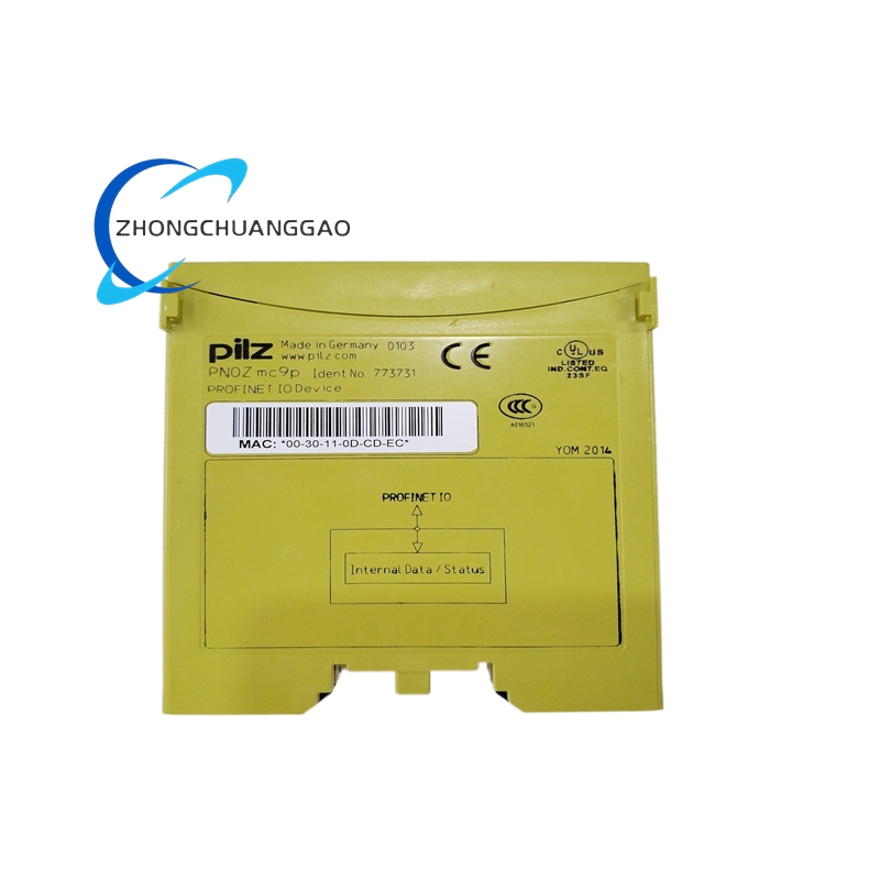
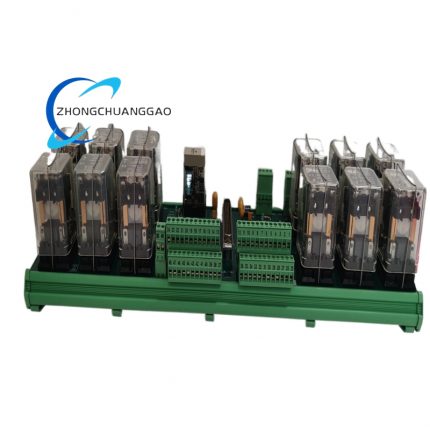
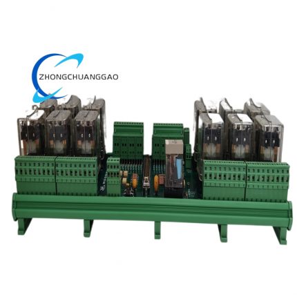
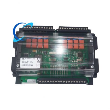
Woodward 9905-973 is an eight-channel independent galvanically isolated relay output modular component developed for Woodward proprietary LinkNet fieldbus control network, matched with MicroNet series governor, turbine controller and genset DCS system. The module receives digital switching command data transmitted from main control unit via LinkNet communication bus, converts bus digital instructions into mechanical relay on/off output signals to drive field on-site solenoid valves, auxiliary contactors, alarm horns and auxiliary equipment loads. Every single channel adopts independent circuit isolation design to eliminate cross-channel interference and ground loop surge damage. Standard 35mm DIN top-hat rail installation structure fits standard industrial control cabinet layout, all channel parameters and relay logic are configurable via official Woodward LinkNet configuration software, widely deployed on gas turbine, steam turbine, diesel generator set and compressor safety auxiliary control loops.
3. Technical Specifications
- Rated Working Power Supply: 18VDC ~ 36VDC, nominal 24VDC DC input, built-in reverse polarity input protection circuit
- Channel Quantity: Total 8 fully independent electrically isolated relay output channels inside single module housing
- Single Channel Relay Contact Rating: 5A @28VDC resistive DC load; 0.5A @15VAC 60Hz alternating current load
- Internal Circuit Galvanic Isolation Voltage: 2500VAC /60s isolation between LinkNet bus side and field relay output side
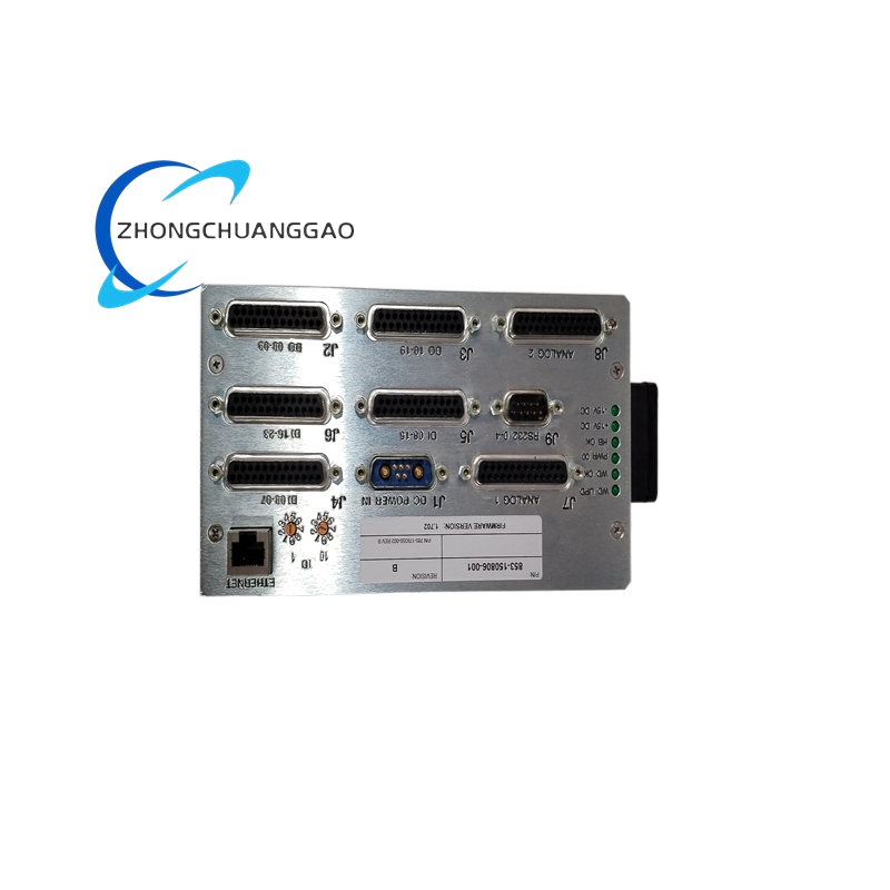
- Communication Interface: Dedicated LinkNet proprietary fieldbus terminal, supports two-wire bus cascade wiring topology
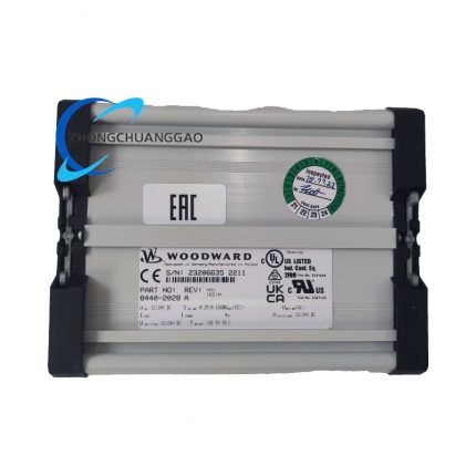
- Overall Outer Dimension: Length 114mm × Width 68mm × Depth 25mm
- Net Single Unit Weight: 200g
- Continuous Rated Operating Ambient Temperature: -40℃ ~ +85℃
- Working Ambient Relative Humidity: 5%~95% non-condensing full temperature range
- Storage Environment Temperature: -45℃ ~ +90℃ sealed dry storage
- Formal Industrial Certification: UL listed, CE EMC compliance, Class I Div.2 hazardous location certification for genset and offshore cabinet installation
- No-load Static Power Consumption: Max 3.2W under all relay coil de-energized state; max 7.8W under full 8-channel relay energized full-load operation
- Wiring Terminal Compatible Wire Specification: AWG24 ~ AWG14 solid/stranded copper control cable
4. Functional Features
- Eight completely separated independent relay channels, each channel executes on-off action independently without electrical coupling or signal crosstalk between adjacent channels.
- Proprietary LinkNet bus communication realizes multi-module cascade expansion on same bus, single LinkNet trunk supports up to 32 pieces of 9905-973 modules for centralized I/O expansion.
- Each channel equipped with independent front-panel LED status indicator; LED lights synchronously once corresponding relay coil energizes and contact closes.
- Full-channel built-in transient surge absorption components at field output terminals to absorb inductive load reverse electromotive force and avoid internal core circuit breakdown.
- All channel output logic, relay delay parameters, bus communication address are editable via Woodward official LinkNet PC configuration software without hardware jumper modification on module body.
- Built-in bus short-circuit automatic protection circuit; single channel field short-circuit only locks corresponding faulty channel without affecting remaining seven channels and total LinkNet bus communication.
- Support hot-swap online replacement under powered LinkNet bus operating state; module plugging will not trigger main control unit system fault alarm.
- Terminal area printed permanent marking to distinguish LINKNET bus wiring terminal and FIELD load output terminal for preventing wrong cross wiring.
5. Performance Parameters
- Single Relay Pull-in Response Time: ≤10ms from valid bus command reception to mechanical contact full closure completion
- Single Relay Mechanical Service Lifespan: ≥10,000,000 no-load switching cycles under rated ambient environment
- Single Relay Electrical Service Lifespan: ≥120,000 full rated contact load on-off operation cycles
- Full unit overall MTBF value under standard industrial rated environment: 256000 continuous operating hours
- Internal bus circuit temperature drift coefficient: ≤9ppm/℃ within full -40℃~+85℃ rated working temperature range
- Terminal screw repeated fastening cycle life: ≥2000 tightening & loosening operations without thread sliding failure
- EMC anti-interference standard compliance: EN61000-6-2 industrial environment electromagnetic immunity specification
6. Material Composition
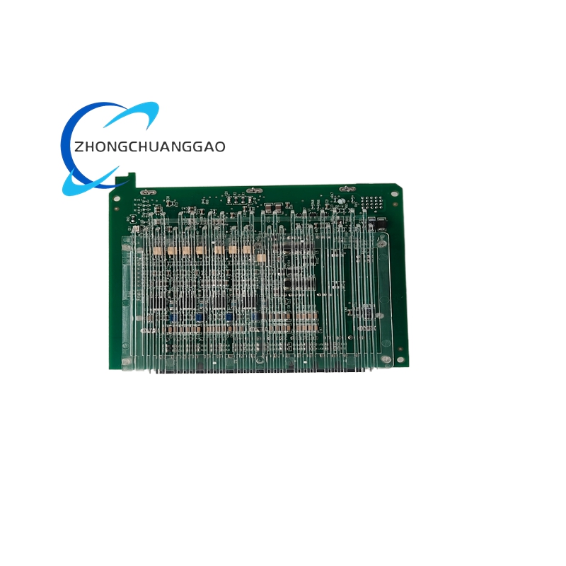
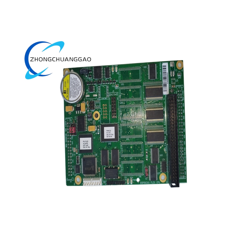
- Main Printed Circuit Board Substrate: FR-4 high Tg flame retardant glass fiber PCB with immersion tin anti-oxidation surface treatment, full SMT surface mount assembly process.
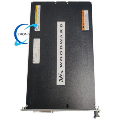
- Outer Module Enclosure Shell: UL94-V0 flame retardant modified ABS engineering plastic casing with anti-aging and oil-resistant formulation.
- Wiring Terminal Components: Nickel-plated solid brass conductive inserts, zinc alloy anti-loose locking screws and PA66 flame retardant terminal base.
- Internal Isolation Component: Epoxy encapsulated miniature isolation transformer for bus and field circuit electrical separation.
- Built-in Electromagnetic Relay: Silver alloy sealed miniature electromagnetic relay with high-temperature resistant coil skeleton.
- Onboard Passive Electronic Components: AEC-Q200 grade TVS transient suppression diodes, X7R multilayer ceramic capacitors, precision metal film fixed resistors.
- Internal Fixed Hardware: Cold rolled steel stamping positioning shrapnel for PCB anti-vibration fixed installation inside plastic housing.
7. Structural Characteristics
- Compact single-width DIN modular integrated structure, split internal space into left LinkNet bus circuit zone and right eight-channel field relay output zone via molded plastic isolation partition.
- Rear casing integrally formed DIN35 standard snap buckle for one-step clamping onto standard top-hat DIN rail without extra fixing accessories.
- Front panel reserved independent LED indicator window corresponding to each relay channel position, permanent high-temperature solvent-resistant silkscreen for part number and terminal definition marking.
- Two groups of separate terminal block layout: upper terminal exclusively for LinkNet bus communication wiring, lower terminal bank for 8-channel field load output wiring with clear zoning separation.
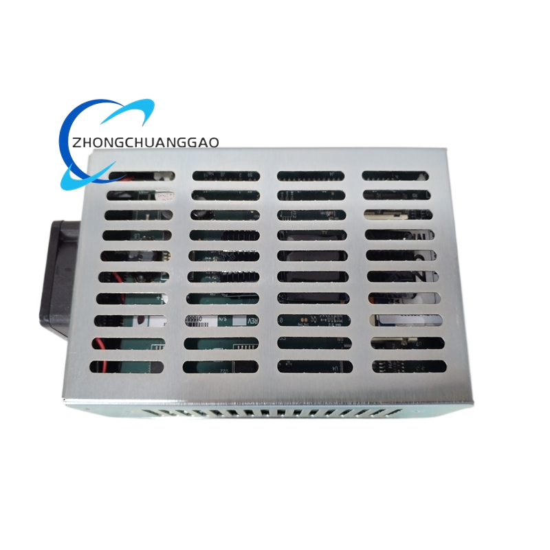
- Top and bottom casing prefabricated strip-shaped tiny ventilation slits for passive natural convection heat dissipation under full-load continuous operation.
- Internal layered fixed PCB design, bus control circuit board and eight-channel relay output board stacked fixed with nylon insulation pillars to reduce internal electromagnetic interference.
8. Working Principle
Step1: LinkNet Bus Command Receiving
Woodward main governor/controller sends discrete switching instruction data via two-wire LinkNet fieldbus to module bus terminal; internal bus receiving circuit decodes target channel address and corresponding on/off control command.
Step2: Isolated Drive Signal Conversion
Decoded digital control signal transmits to isolated drive circuit; isolation transformer completes electrical separation between bus control side and field output side to block ground potential difference interference.
Step3: Internal Relay Coil Energization
Valid isolated drive voltage energizes corresponding target channel internal relay coil to generate electromagnetic pull-in force and drive mechanical contact state switching.
Step4: Field Load Circuit Switch Execution
Relay contact completes open/close state conversion to switch external field connected solenoid, contactor or alarm equipment power supply circuit, realizing equipment start-stop control.
Step5: Local Status Visual Feedback
Corresponding channel front-panel LED indicator synchronously lights up to feedback real-time relay working state for on-site maintenance inspection.
Step6: Surge Fault Suppression
Inductive load reverse spike voltage generated at field terminal during contact breaking is absorbed by built-in TVS protection component to protect internal relay and PCB circuit from overvoltage damage.
9. Advantage Highlights
- Eight-channel integrated compact design greatly reduces DIN rail occupied space versus eight independent single-channel relay modules and lowers spare part inventory cost for end user maintenance management.
- Dedicated LinkNet bus communication matches full range Woodward MicroNet governor products to realize seamless system integration without extra protocol conversion gateway.
- High 2500VAC port-to-port isolation rating completely eliminates ground loop interference between control cabinet earthing and field equipment grounding system to avoid unexpected relay misoperation.
- Wide 18~36VDC power input range adapts industrial site backup battery voltage fluctuation under grid emergency power failure switching status of genset control room.
- Software configurable channel address and output logic cancels hardware jumper setting, improving field debugging efficiency and reducing wiring modification cost.
- Hot-swap function allows online fault module replacement without shutting down whole DCS control system to cut equipment downtime loss.
- Wide -40℃~+85℃ working temperature range adapts outdoor generator set container cabinet and high-temperature engine room harsh installation environment.
10. Applicable Industries
- Power Generation Industry: Diesel/gas reciprocating genset auxiliary valve control, gas/steam turbine auxiliary interlock, power plant emergency shutdown auxiliary equipment switching control
- Petrochemical Industry: Refinery waste heat power unit, chemical plant gas compressor safety auxiliary solenoid valve on/off control
- Offshore Oil & Gas Industry: Offshore platform genset cabin, FPSO onboard gas engine auxiliary equipment interlock control
- Landfill & Biogas Energy Industry: Biogas generator set fuel valve and exhaust protection equipment discrete control
- Mining Industry: Mine backup diesel generating set safety interlock and ventilation auxiliary equipment switching control
- Distributed Energy Industry: Natural gas distributed power station, cogeneration unit auxiliary control cabinet I/O expansion application
11. Model Series Affiliation
- Parent Core Product Series: Woodward 9905 LinkNet Series I/O Expansion Module Family
- Same Series Sibling Standard Models:
- 9905-971: 4-channel LinkNet relay output compact module
- 9905-975: 16-channel LinkNet digital input collection module
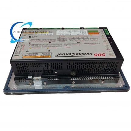
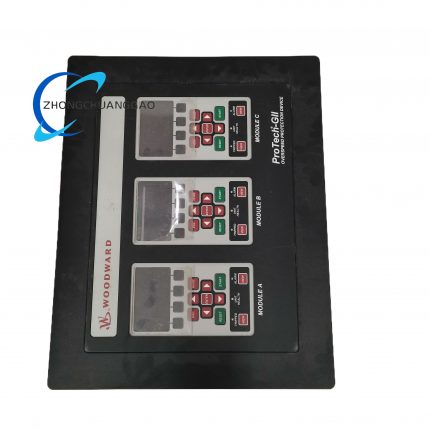
- Compatible Matching Host Equipment: Woodward 505/505E digital governor, MicroNet Plus turbine controller, ProTech overspeed safety controller
12. Installation Requirements
- Mounting Environment Standard: Install exclusively inside closed ventilated industrial control cabinet; direct installation inside high-corrosion acid/alkali gas enclosed space is forbidden without sealed protective housing.
- DIN Rail Mount Specification: Snap rear integrated buckle onto standard 35mm top-hat DIN rail and press downward until full locking without loose sliding displacement.
- Wiring Classification Regulation: Upper LINKNET terminal wiring only connects to Woodward main controller LinkNet bus trunk; lower field terminals connect strictly to on-site load equipment, cross wiring of two terminal groups is permanently prohibited.
- Field Load Cable Specification: Inductive load wiring must adopt shielded twisted-pair control cable; cable shielding layer single-point grounding only at control cabinet PE protective earth terminal.
- Heat Dissipation Clearance Requirement: Minimum 4mm vacant gap reserved between adjacent mounted modules for natural convection heat dissipation inside cabinet.
- Pre-install Confirmation: Verify field load actual working voltage and load current are within module rated contact specification before wiring construction execution.
13. Use & Maintenance Precautions
- Strictly prohibit overrated high voltage/current load access into field output terminals; over-spec load permanently burns internal relay contact and voids module certification.
- All field wiring disassembly or modification work can only be finished after cutting off module 24VDC power supply; live wiring easily causes internal circuit short-circuit damage.
- Quarterly regular maintenance only uses dry lint-free cloth to wipe outer casing and terminal dust; alcohol, acetone and organic solvent direct contact with plastic housing and PCB is forbidden to prevent shell aging deformation.
- Unused spare modules must be sealed inside original factory anti-static shielding bag and stored under 10℃~35℃ dry constant temperature environment; damp open-air long-term storage is prohibited to avoid internal relay spring rust failure.
- Fault replacement on critical safety interlock loop only allows original factory genuine Woodward 9905-973 module; third-party refurbished or imitation substitute products cannot access genset safety control loop.
- Avoid high-frequency inverter, arc welding equipment installed within 30cm distance of mounted control cabinet to prevent strong electromagnetic radiation triggering abnormal relay false action.
- When carrying module for maintenance, operators must wear anti-static wristband to release body static charge and prevent electrostatic breakdown of onboard precision semiconductor components.


")
")


-430x430.jpg)
-430x430.jpg)
-1-430x430.jpg)

Reviews
There are no reviews yet.