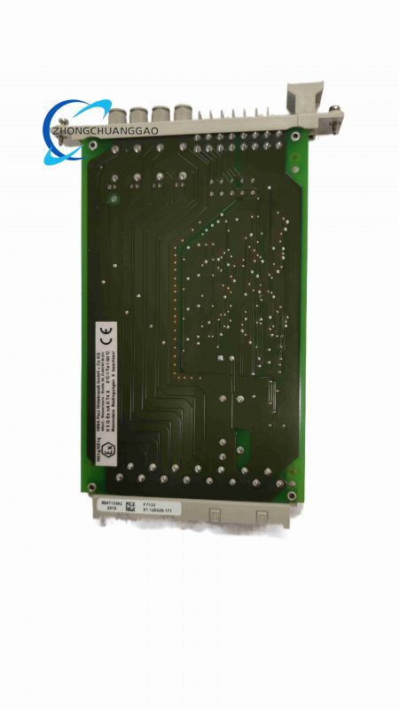
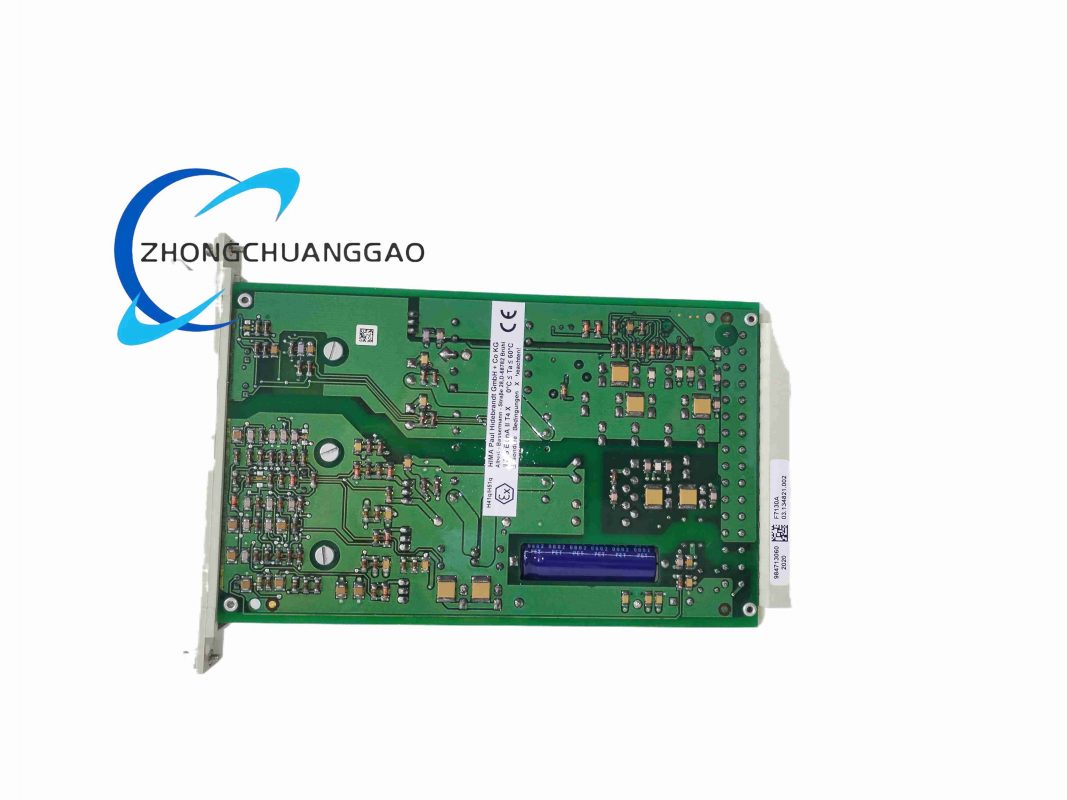
HIMA F7133
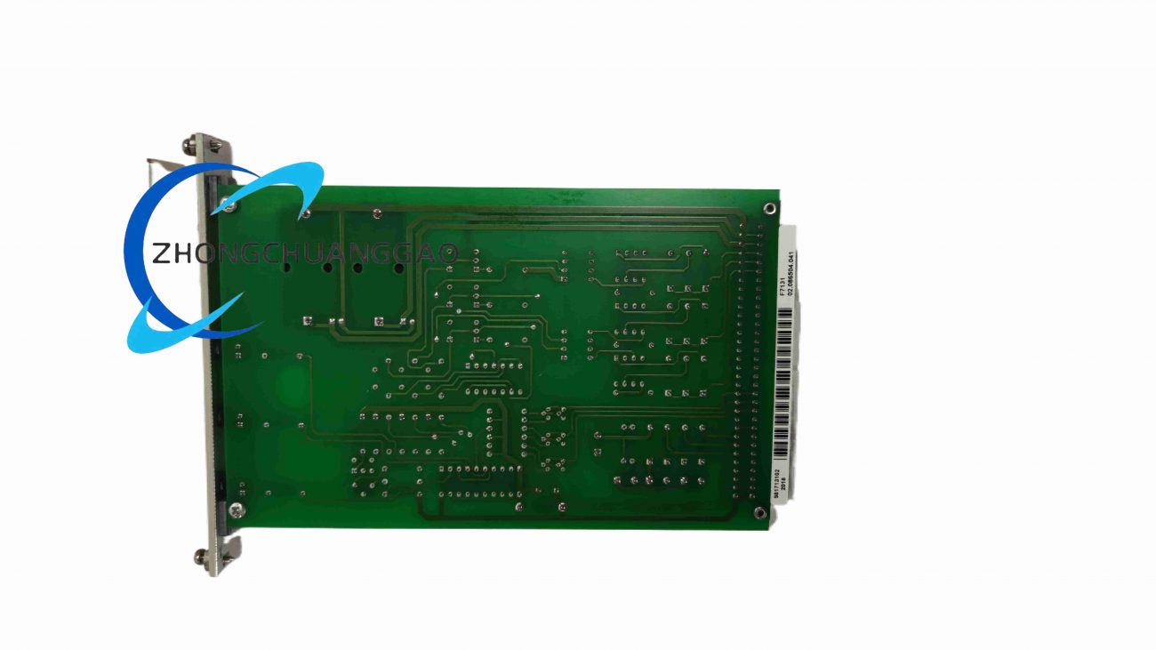
HIMA F7131 981713102
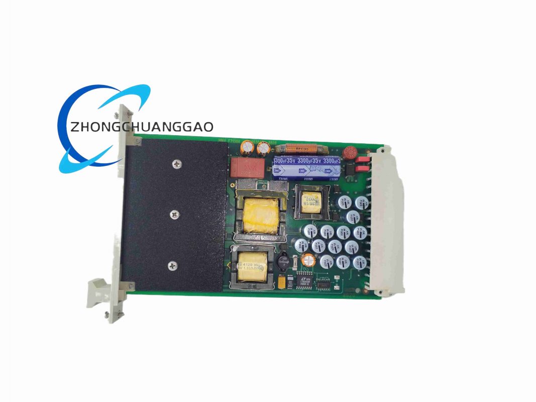
HIMA F7130A
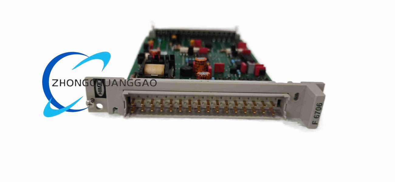
HIMA F6706
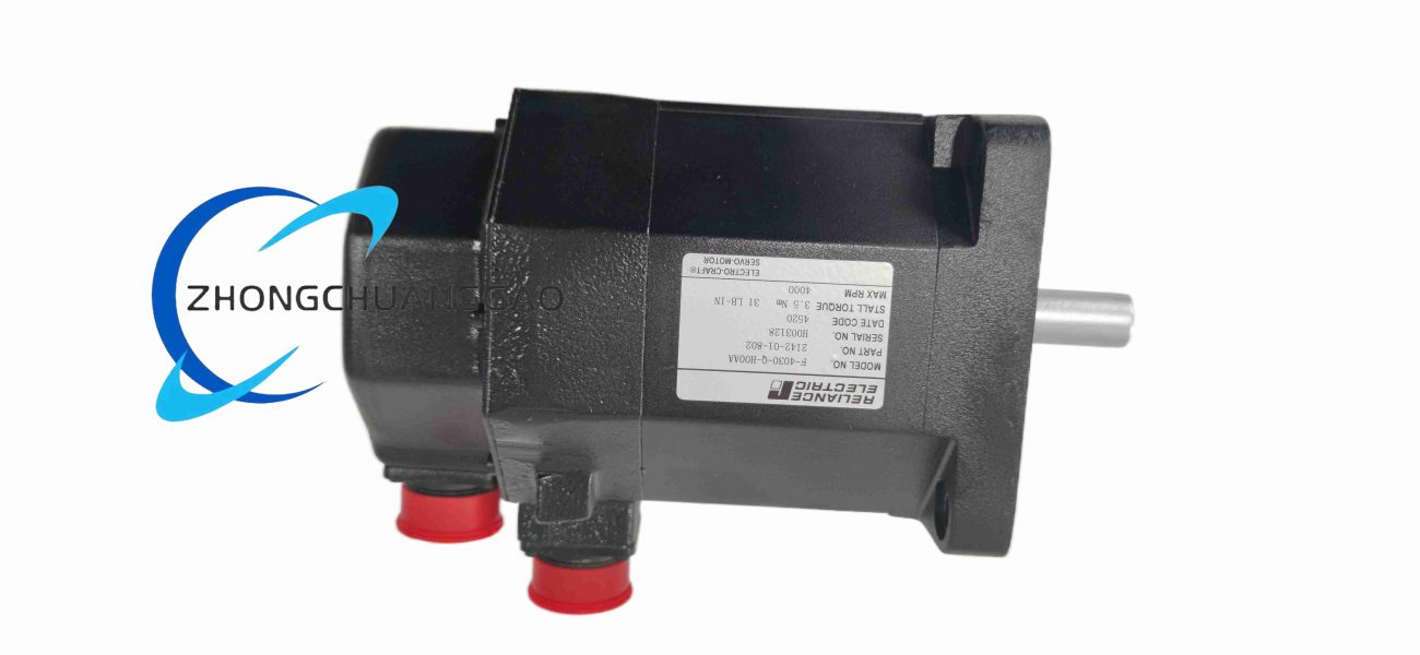
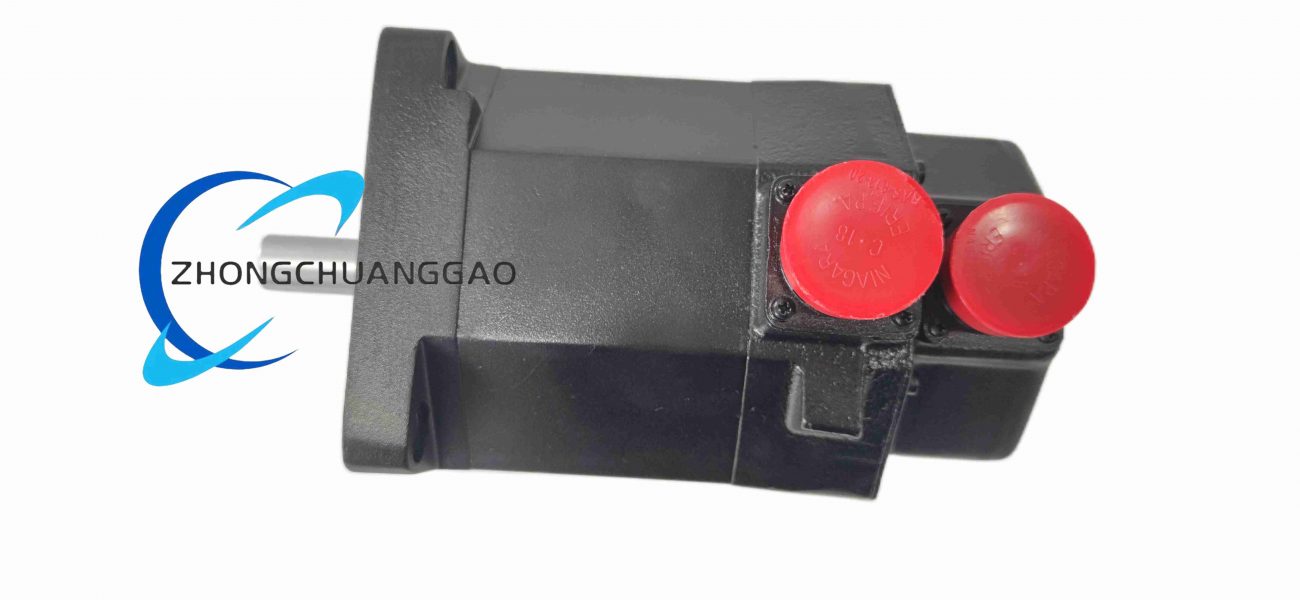
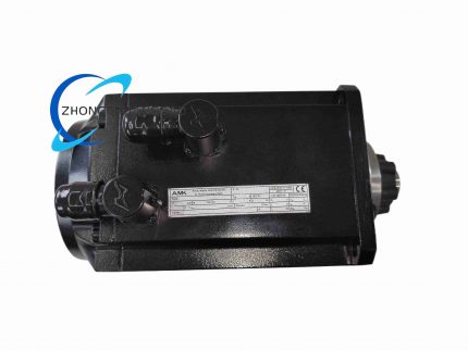
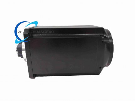
Electro-Craft F-4030-Q-H04AA
HIMA F3503SILWORX
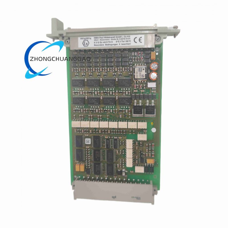
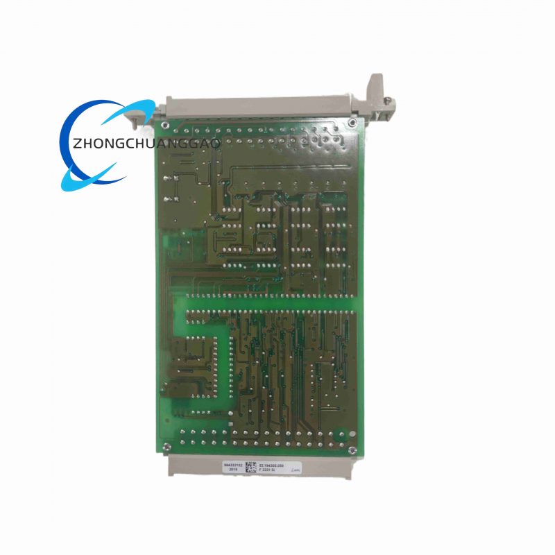
HIMA F3331
HIMA F3240
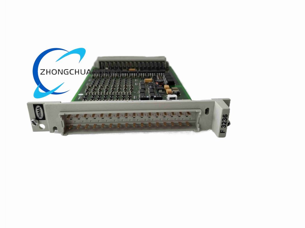
HIMA F3236
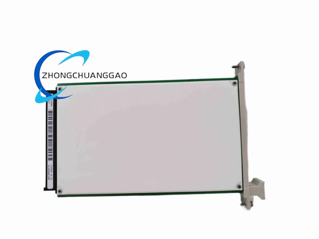
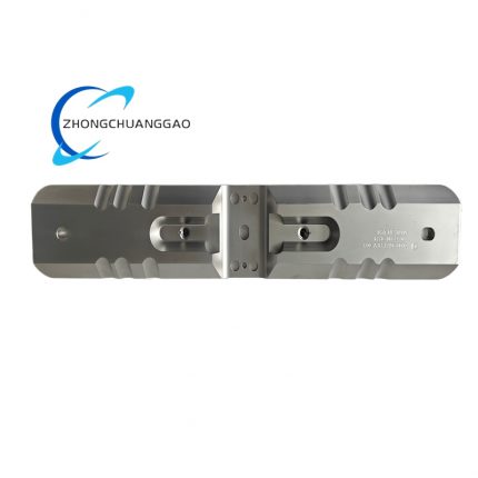
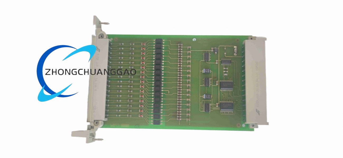
HIMA F3226A
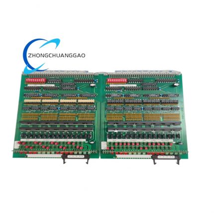
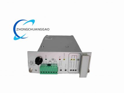
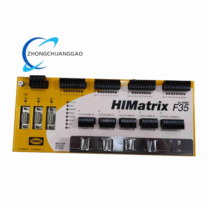
Product Introduction: Enhanced density or specialized digital input/switching amplifier module for HIMA HIMax and HIMatrix SIS, providing SIL 3 compliant signal conditioning and acquisition, often referenced as 32-channel high-density or 2-channel amplified variant depending on system context (F3226A commonly 32-ch DI in HIMax F3200+ series; F3226 as 2-ch switch amp in other contexts, but F3226A specified here as SIS module).
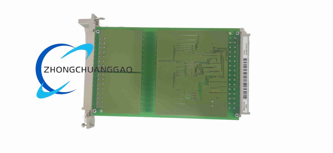
HIMA F3221 984322102
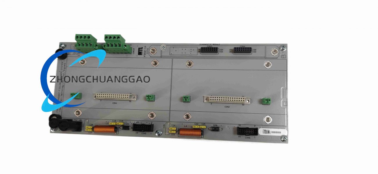
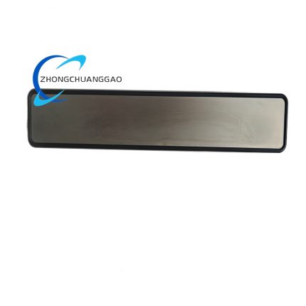
MTL F860-CA
-
Product Name: MTL F860-CA IOTA (Instrumentation Outer Terminal Assembly)
-
Product Introduction: Passive Input/Output Termination Assembly designed for mounting MTL F801/F802 Fieldbus Power Conditioner modules, providing redundant power distribution and termination for 8 Foundation Fieldbus H1 segments in Honeywell Experion Series C or equivalent racks.