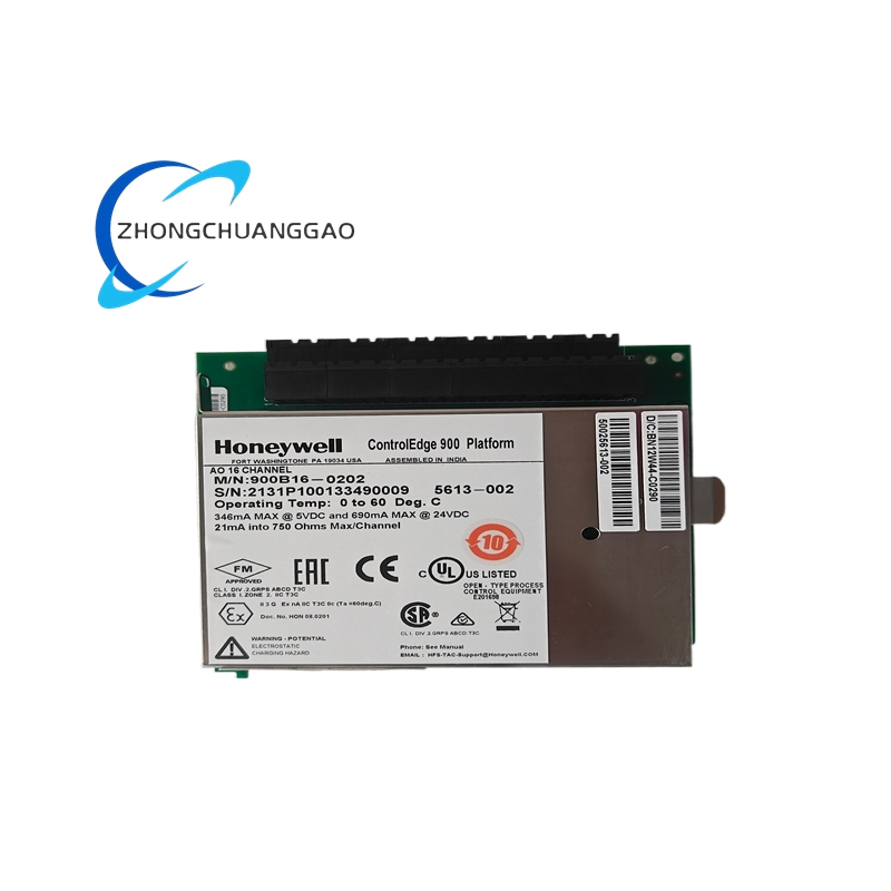
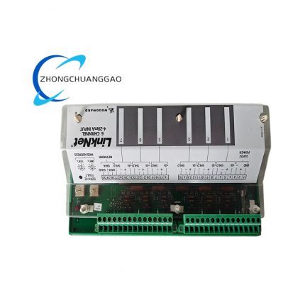
Product Introduction
- This device is rack-mounted industrial isolated analog input communication module designed for centralized collection of on-site industrial analog process signals and protocol conversion transmission to upper-level DCS, PLC or SCADA host system.
- The module converts standard field 4–20mA / 0–5VDC analog process signals into digital communication frame data, completes galvanic isolation between field loop side and internal communication bus side to block surge interference from field long-distance wiring.
- All collected real-time analog measurement values, channel fault status and module operating parameters are packaged into standardized industrial bus protocol and uploaded via dedicated backplane communication bus to system main controller.
- The product complies with IEC61131-2 industrial automation and IEC61000 series EMC standards, designed for continuous 24-hour uninterrupted fixed installation inside industrial control cabinet for process industry analog signal centralized acquisition.
3. Model Series Information
- Fixed Core Model Code: 8903-AI-00
- Parent Product Series: 8903 Universal Rack-based I/O & Communication Module Series
- Corresponding Derivative Series Models:
- 8903-AO-00: Isolated Analog Output Communication Module variant
- 8903-DI-00: Digital Input Communication expansion module
- 8903-DO-00: Digital Output Communication expansion module
- Standard PCB Hardware Revision: Rev.A ~ Rev.D, all revision versions retain consistent mounting dimension, pin definition and full electrical parameter specifications.
4. Technical Specifications
4.1 Power Supply Specification
- Internal Backplane Rated Operating Supply Voltage: 24VDC ±10% supplied from system rack backplane bus
- Module Rated Total Power Consumption: 3.8W maximum under full-channel loaded working status
- Internal isolated auxiliary loop excitation power: Built-in isolated 24VDC loop power supply for field two-wire transmitter, single channel maximum supply output current 32mA per input channel.
4.2 Analog Input Channel Specification
- Total Isolated Analog Input Quantity: 8 galvanically isolated single-ended analog input channels
- Supported standard input signal types:
- 4~20mA DC current signal (industry standard two-wire transmitter signal)
- 0~5VDC / 1~5VDC voltage analog signal
- Each channel independent isolation withstand voltage: 2500VAC dielectric isolation between field side and internal module logic circuit
4.3 Communication Bus Specification
- Internal rack backplane communication interface: Proprietary high-speed parallel backplane bus dedicated to 8903 series rack system, fixed bus communication rate 2Mbps
- External optional auxiliary communication port: Terminal-side RS485 physical interface, factory default Modbus RTU protocol with configurable baud rate from 2400bps up to 19200bps
- Module station address range: Hardware DIP switch configurable station address 1~99 without software modification requirement.
4.4 Environmental & Physical Dimension Specification
- Certified Operating Ambient Temperature Range: 0℃ ~ +60℃
- Storage & transportation temperature range: -40℃ ~ +85℃
- Valid operating relative humidity scope: 5%~95%RH non-condensing environment only
- Overall outer dimension: 132mm(H) × 85mm(W) × 28mm(D)
- Single unit net weight: 0.32kg
- Protection grade of module main body: IP20; exposed wiring terminal area protection grade: IP00.
5. Function Features
- Independent channel hardware open-circuit and short-circuit automatic detection function; each abnormal channel generates fault flag and transmits fault message via communication bus to upper controller instantly.
- Built-in digital average filtering algorithm with user programmable filter sampling depth to eliminate industrial field power frequency interference and transient signal burr noise.
- Nonvolatile onboard EEPROM storage for channel range configuration data, calibrated coefficient and module communication address; all configuration data permanently reserved after complete power failure without parameter loss.
- Front panel multi-color LED status indicator group: Green LED for normal power supply and communication running, Red LED for channel hardware fault or communication breakdown, Amber LED for single-channel signal out-of-range warning.
- Onboard DIP switch group realizes rapid selection of input signal type (current/voltage) without upper computer configuration software operation.
- Real-time channel raw data, engineering scaled value and diagnostic information cyclic uploading via backplane communication bus following fixed system communication scheduling cycle.
- Supports field engineering unit scaling programming; users set upper/lower engineering range for every individual channel to convert raw electrical value directly into actual physical process value.
- Module hot-swap compatible with matched standard 8903 series installation rack; single module plug replacement does not interrupt normal running status of remaining modules on the same rack.
6. Performance Parameters
- Full scale basic measurement accuracy: ±0.1%FS under standard 25℃ rated calibration environment
- Single channel ADC conversion cycle: Fixed 2.2ms per independent channel sampling conversion
- Calculated rated MTBF value: ≥350000 continuous working hours within specified operating temperature range
- Full range temperature drift coefficient: ≤8ppm/℃ across complete 0℃~60℃ working temperature span
- Analog input channel common-mode noise rejection ratio: ≥130dB at industrial standard 50Hz power frequency
- Communication bus data transmission error rate: Zero verified bit error under standard rated EMC test environment.
7. Material Composition
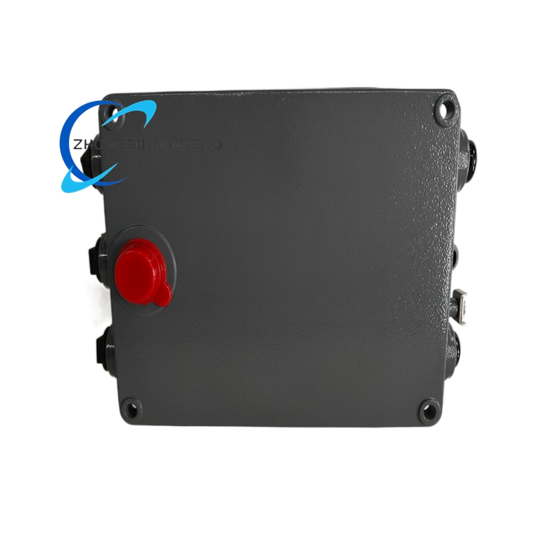
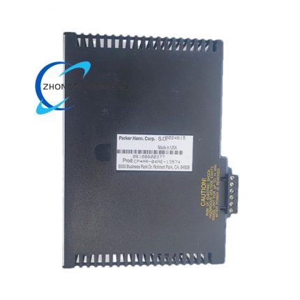
- Outer module plastic frame and front panel housing: UL94-V0 flame retardant black modified ABS engineering plastic with anti-ultraviolet and low temperature anti-brittle formula.
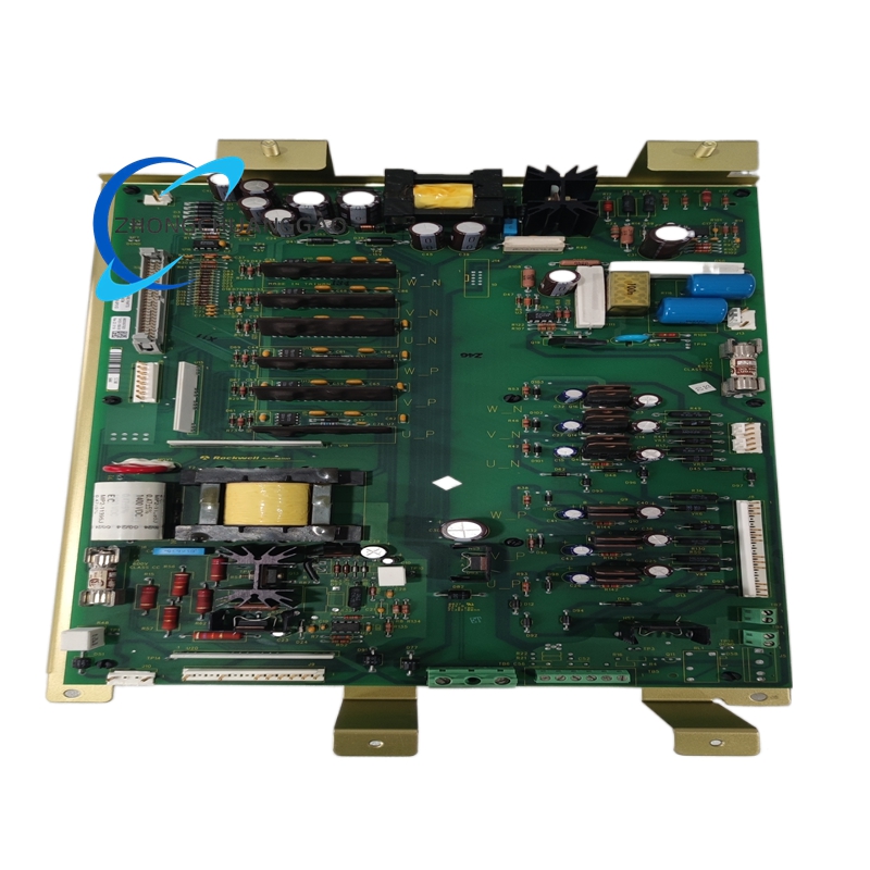
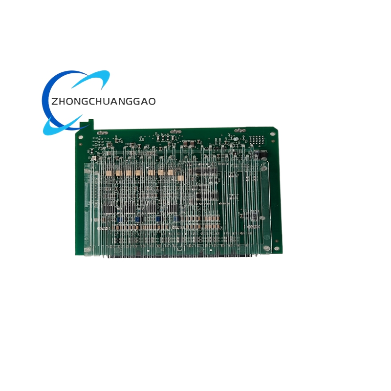
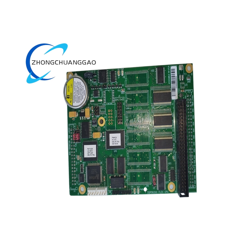
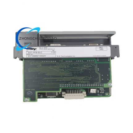
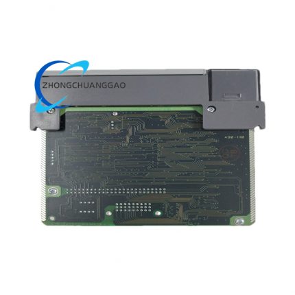
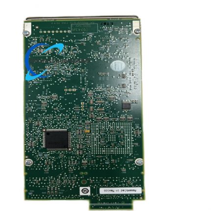
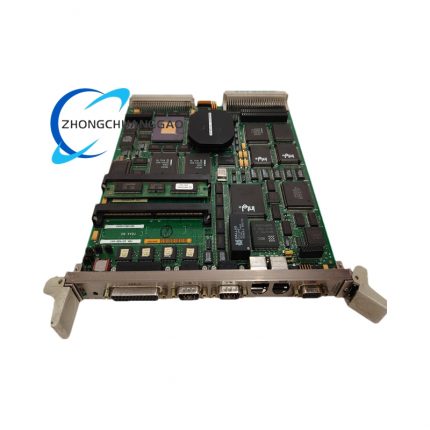
- Main control PCB substrate: High-Tg FR-4 industrial glass fiber printed circuit board; entire PCB surface coated with acrylic three-proof conformal coating for moisture, sulfurization and mold prevention.
- Core signal isolation components: AEC-Q102 certified optocoupler chips for per-channel galvanic isolation, industrial wide-temperature Sigma-Delta multi-channel ADC converter.
- Passive electronic components: Precision metal film fixed resistors, high temperature solid tantalum capacitors, high frequency multilayer ceramic decoupling capacitors rated -40℃~+125℃ working temperature.
- External wiring terminal base: Glass fiber reinforced PA66 nylon terminal blocks equipped with silver-plated copper alloy spring conductive terminals; terminal function identification marked by permanent laser etching.
- Internal storage component: Industrial grade serial EEPROM nonvolatile memory chip for configuration parameter storage.
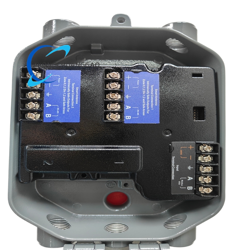
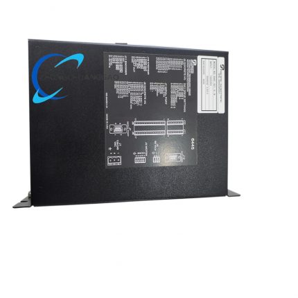
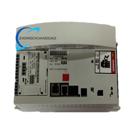
8. Structural Characteristics
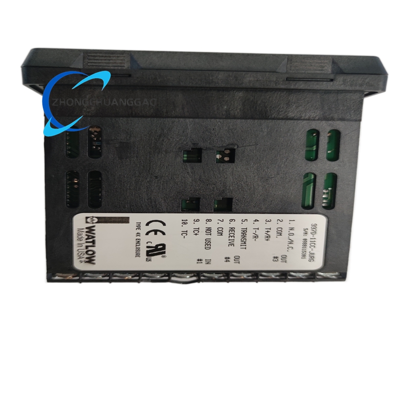
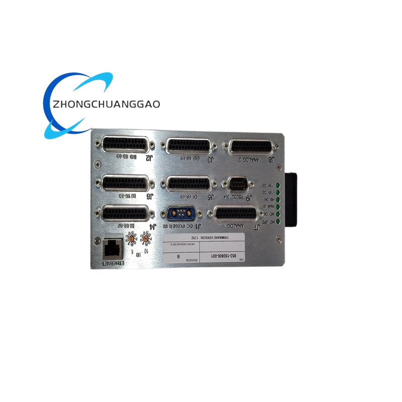
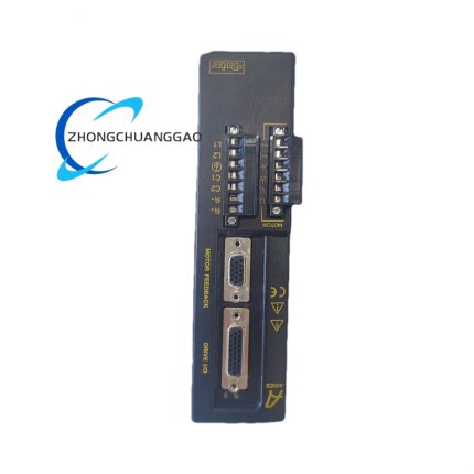
- Three-layer layered compact internal layout: Front panel indicator & setting switch layer, middle analog signal conditioning & digital control PCB layer, rear field signal wiring terminal layer.
- Front panel centralized layout: Three-color LED indicator bank, signal type selection DIP switch set, module station address setting DIP switch array.
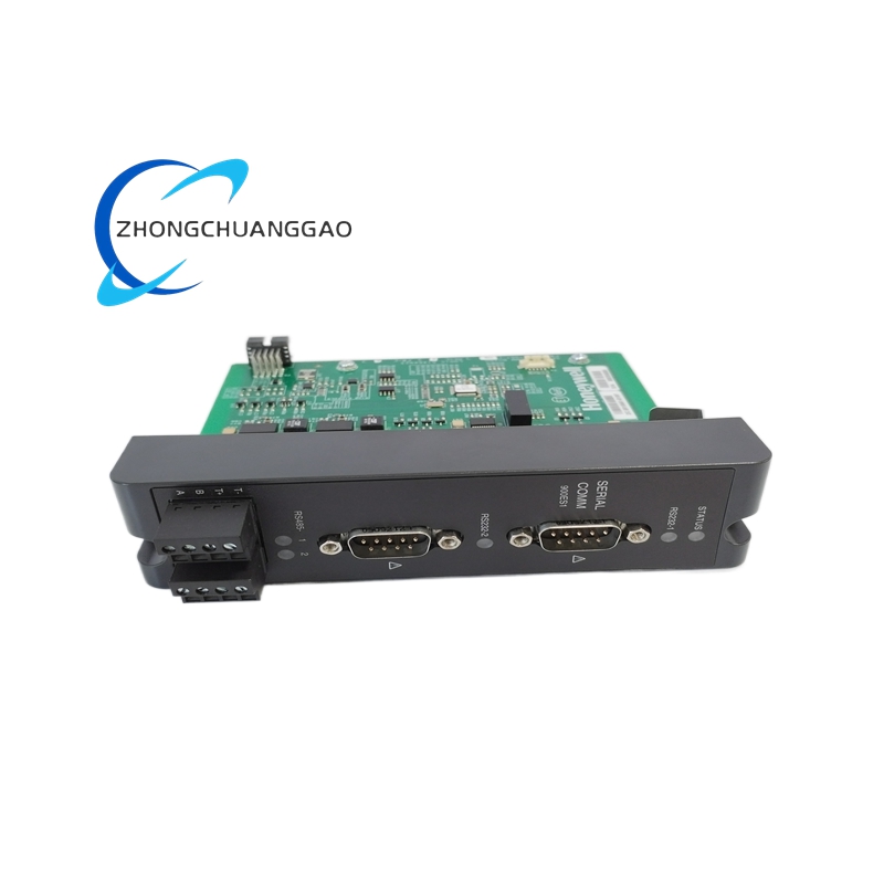
- Rear side fixed partitioned terminal layout: 8-channel analog input terminal area, RS485 auxiliary communication terminal area; plastic isolation ribs separate different functional terminal regions to prevent accidental short circuit.
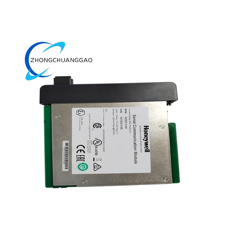
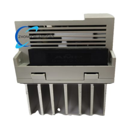
- Standard plug-in card structure matching dedicated 8903 series system rack card slot; plastic positioning buckle on card edge completes mechanical locking after full insertion into rack slot to avoid loose vibration during long term operation.
- Independent ground partitioning layout on PCB: Analog signal ground and digital control ground adopt separated wiring layout to suppress crosstalk interference between analog acquisition loop and digital communication circuit.
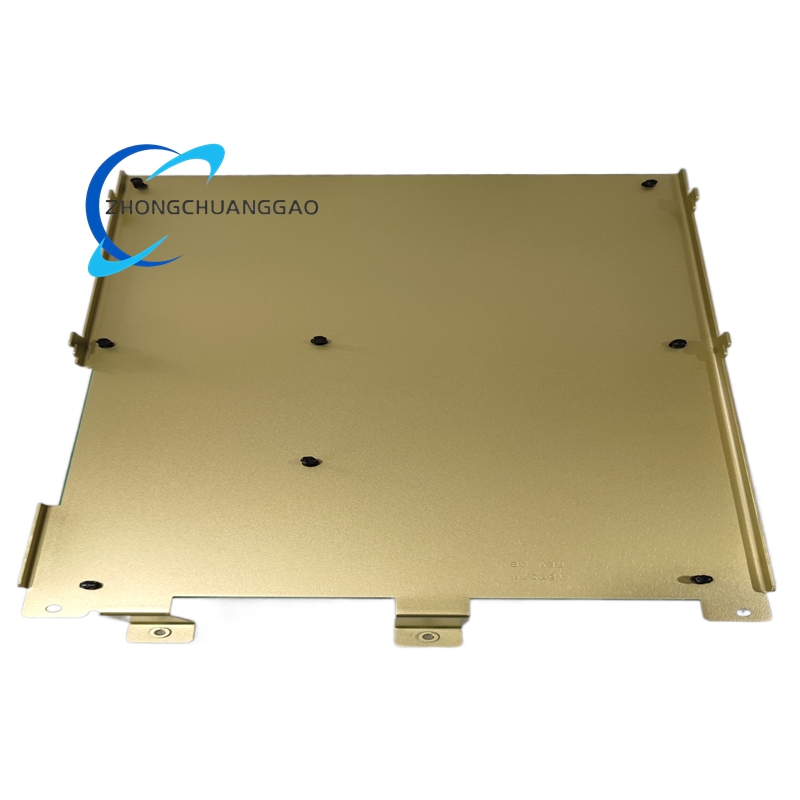
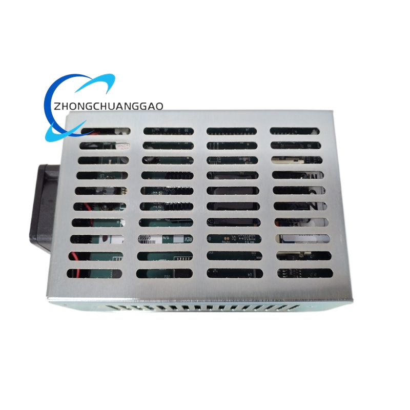
- Passive natural convection heat dissipation air gap reserved between PCB and outer plastic casing for continuous high-load operating heat dissipation.
9. Working Principle
- Field Signal Input Stage: On-site industrial two-wire transmitters or voltage sensors output 4–20mA / 0–5VDC analog signal into corresponding isolated input channel terminals; signal passes through overvoltage protection circuit and precision impedance matching conditioning circuit before sending to isolated ADC chip.
- Analog-Digital Conversion Stage: Per-channel isolated Sigma-Delta ADC converts continuous analog physical signal into discrete digital sampling value; built-in digital filter processes sampled data to remove abnormal transient noise per pre-set filter parameters.
- Data Scaling & Logic Processing Stage: Core industrial MCU reads filtered digital data, calls pre-stored channel scaling coefficient stored in EEPROM to convert raw digital data into actual engineering physical value; MCU judges whether measured value exceeds pre-set range or channel has open/short fault state.
- Communication Data Packaging Stage: MCU packs real-time channel measured data, single-channel fault codes and module operating status into standard communication data frame complying with backplane bus protocol.
- Data Upload Transmission Stage: Packaged data frame is transmitted via rack backplane high-speed communication bus to system main controller; when external RS485 Modbus function is activated, same data is synchronously output to external fieldbus terminal via auxiliary RS485 port.
- Status Indication Stage: MCU drives corresponding front panel LED indicators to display real-time running, fault or over-range state according to internal logic judgment result.
10. Advantage Highlights
- Per-channel independent 2500VAC galvanic isolation design completely isolates high surge voltage induced from field long-distance cables, eliminating cross-channel interference and module breakdown risk caused by field abnormal overvoltage intrusion.
- Hot pluggable rack installation design allows on-site module maintenance and replacement without shutting down entire rack system power supply, shortening equipment downtime for industrial continuous production sites.
- Onboard nonvolatile parameter storage retains all configuration information permanently; equipment resumes full functional status automatically after power recovery without repeated parameter configuration work.
- Multi-layer hardware overvoltage, overcurrent and short-circuit protection circuit is integrated inside every input channel to avoid component burnout caused by field wiring misconnection.
- Dual communication design combining internal backplane bus and external RS485 Modbus realizes flexible system topology selection to match centralized rack installation or distributed field cabinet installation scenarios.
- Compact plug-in structure reduces cabinet internal occupied space and wiring workload compared with split-type standalone signal collector plus external communication converter solution.
- Full compliance with international industrial EMC and safety certification standards to satisfy global process factory indoor cabinet installation specifications.
11. Applicable Industries
- Petrochemical Industry: Refinery production workshop, chemical raw material storage tank area temperature/pressure transmitter signal centralized collection and communication transmission.
- Power Generation Industry: Thermal power plant auxiliary water treatment system, boiler auxiliary instrument analog signal remote data uploading.
- Water & Wastewater Treatment Industry: Sewage treatment plant PH, dissolved oxygen, liquid level transmitter signal acquisition for SCADA system docking.
- Pharmaceutical Fine Chemical Industry: Pharmaceutical synthesis workshop raw material pipeline pressure and flow field instrument signal centralized data transmission.
- Metallurgy Industry: Smelting furnace auxiliary cooling system pressure, temperature analog signal remote communication collection.
- Food & Beverage Processing Industry: Automated production line tank level, pipeline flow instrument signal DCS system data upload.
- Natural Gas Distribution Industry: Gas station pipeline pressure and flow transmitter data acquisition for remote monitoring platform connection.
12. Installation Requirements
- Cabinet Environment Requirement: Install module inside closed industrial control cabinet; cabinet internal ambient temperature must remain within 0℃~+60℃, prohibit installation near heat-generating components such as power transformers and braking resistors.
- Mechanical Mounting Specification: Insert module along dedicated 8903 series rack card slot guide rail, push fully into slot then lock edge plastic buckle to complete fixed positioning; maintain minimum 15mm upper and lower gap between adjacent modules for heat dissipation airflow circulation.
- Field Signal Wiring Standard: All analog input field cable uses shielded twisted pair wire; cable shielding layer executes single-point grounding only at cabinet terminal side, field instrument side shielding end remains suspended open circuit.
- Wire Cross-section Specification: Field analog signal wiring adopts copper conductor with cross-section ≥0.5mm²; RS485 communication bus wiring uses dedicated twisted pair communication cable with cross-section ≥0.75mm².
- Communication Bus Wiring Rule: External RS485 Modbus bus applies daisy-chain wiring topology; install 120Ω terminal matching resistor at two extreme endpoints of total bus trunk to eliminate signal reflection distortion.
- Hazardous Area Installation Rule: For Zone2 hazardous classified cabinet installation, all external field instrument wiring must pass certified explosion-proof junction box before accessing module input terminals; direct installation inside Zone0/Zone1 hazardous area is prohibited.
13. Use Precautions
- Pre-power-on Inspection Rule: Confirm backplane rack 24VDC power supply matches rated specification before module power-on; forbid connecting higher voltage directly to backplane socket to prevent internal circuit permanent damage.
- Parameter Setting Regulation: Complete DIP switch signal type and station address configuration under full power-off state; parameter modification during powered running will not take effect until module power cycle restart.
- Calibration Operation Condition: Complete full-channel accuracy calibration under stable ambient temperature 23℃±2℃; calibration execution under ultra-high/low temperature environment is forbidden to guarantee measurement precision.
- Maintenance Operation Specification: Cut off corresponding rack backplane power supply before module disassembly maintenance inside hazardous classified area; live plug-in and unplug of field signal terminals during powered running is prohibited.
- Spare Module Storage Standard: Uninstalled spare modules are stored in constant temperature dry warehouse with ambient humidity below 95% non-condensing; long-term storage in high humidity, corrosive gas environment is prohibited.
- Firmware Upgrade Restriction: Internal module firmware update is only available via manufacturer official dedicated configuration software; burning unknown third-party modified firmware is forbidden to avoid abnormal communication and channel function failure.
- Daily Cleaning Specification: Only dry anti-static lint-free cloth is allowed to wipe front panel and terminal surface dust; direct contact of PCB and internal terminals with liquid cleaning solvent is permanently prohibited.
- Overload Usage Ban: Forbid external field two-wire transmitter drawing load current exceeding 32mA per single channel; continuous over-current load causes internal channel excitation power circuit permanent damage.

")
")


-430x430.jpg)
Reviews
There are no reviews yet.