Product Introduction
- This unit is an integrated industrial-grade device integrating programmable motion indexer and bipolar chopper stepper drive circuit, exclusively engineered for closed-loop/open-loop high-precision 4-phase hybrid stepper motor motion control.
- The product merges motion programming logic, digital step subdivision processing and power drive output inside single compact casing, eliminating extra standalone indexer hardware to reduce cabinet wiring quantity and system fault points.
- It executes customized motion sequences via proprietary Stepper BASIC programming language, receives external trigger signals via multi-channel digital I/O terminals, and completes real-time motor speed, position and torque closed-loop regulation matching matched stepper motors.
- Designed per North American UL508C and European CE industrial automation safety standards, targeted for continuous long-cycle fixed installation inside electrical control cabinets for automated production equipment motion execution.
3. Model Series Information
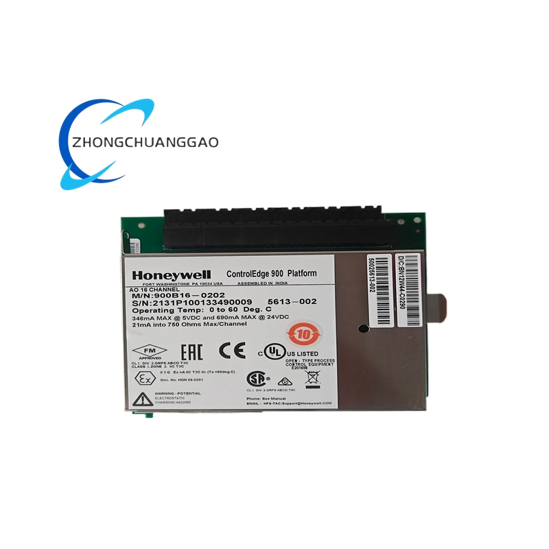
- Fixed Core Model Code: 6445-001-K-N
- Parent Product Series: Pacific Scientific Standard 6445 Integrated Indexer-Drive Series
- Corresponding Derivative Models: 6445-001-N-N (differentiated by internal firmware version and terminal configuration), 6445-002-K-N (dual-axis expansion variant), 6445-003-K-N (enhanced high-current output version)
- Hardware Revision Range: Factory standardized PCB revision covers Rev.B ~ Rev.E, all revisions maintain identical mounting dimension and core electrical parameters
4. Technical Specifications (Core Data Bold Formatted)
4.1 Input Power Specification
- Rated AC Input Voltage: 120VAC / 240VAC, 50Hz / 60Hz universal input, no internal hardware modification required for cross-voltage switching
- Internal Auxiliary Isolated DC Power Output: Fixed 24VDC, 1.2A max load, dedicated power supply for external sensor and digital input equipment
- No-load Static Power Consumption: 18VA maximum; Full rated output load power consumption: 82VA maximum
4.2 Drive Output Electrical Parameters
- Per-phase RMS Adjustable Output Current: 0.625A ~ 5.0ARMS, set via onboard 3-position DIP toggle switch; Peak subdivision output current reaches 7.1A per phase
- Supported stepper motor specification: Standard 1.8° step-angle 4-phase bipolar hybrid stepper motor; step resolution programmable from 200 steps/rev up to 51200 steps per mechanical revolution via digital microstepping setting
- Internal chopper switching frequency: Fixed 20kHz high-frequency PWM chopper control mode
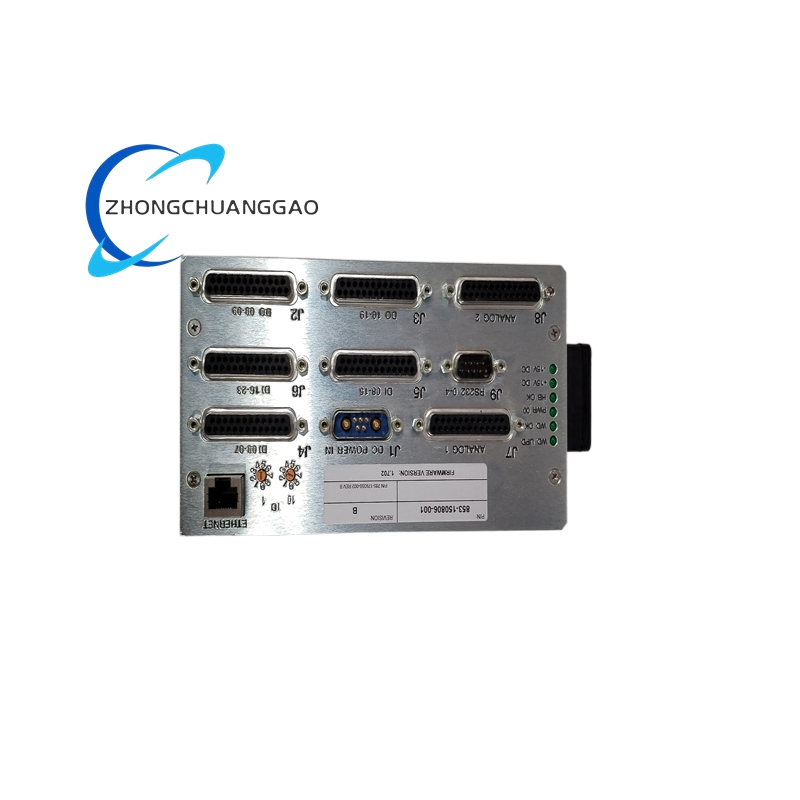
4.3 Digital I/O Terminal Specification
- Programmable Digital Input Channels: 16 opto-isolated sinking/sourcing input terminals, rated compatible input voltage range: 5VDC ~ 30VDC industrial level
- Programmable Digital Output Channels: 12 transistor-type isolated output terminals, single channel continuous load current 0.5A@30VDC, used for external solenoid valve, indicator lamp and auxiliary equipment linkage control
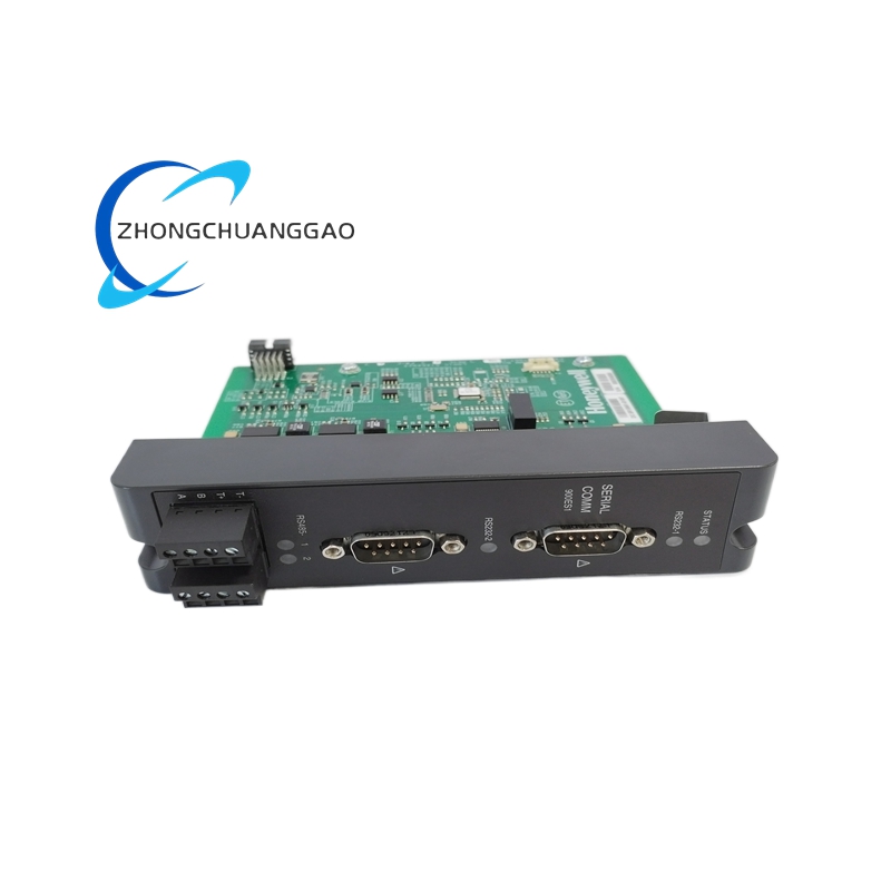
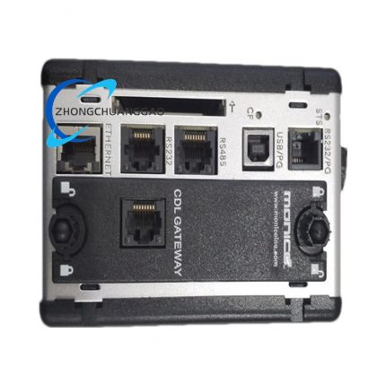
4.4 Communication Interface Specification
- Primary serial communication port: Dual physical interface of RS232 + RS485, fixed factory default baud rate 9600bps, supports single-axis point-to-point and multi-drop multi-axis bus networking connection
- Internal storage configuration: 12KB battery-backed nonvolatile RAM, permanently stores user motion programs, axis parameter data and preset motion profiles after power outage without data loss
4.5 Environmental & Physical Specification
- Rated Operating Ambient Temperature Range: 0℃ ~ +50℃; Storage and transportation temperature range: -40℃ ~ +70℃
- Allowable operating relative humidity: 0% ~ 95%RH, non-condensing ambient environment only
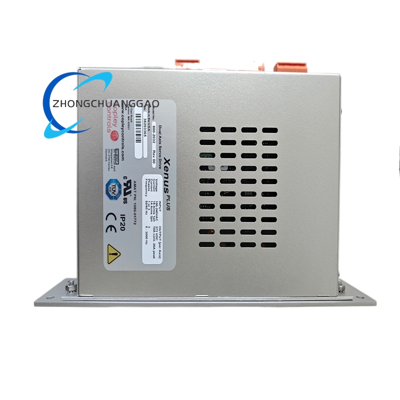
- Overall outer dimension: 220mm (Height) ×128mm (Width) ×72mm (Depth); Net single unit weight: 1.98kg
- Cabinet mounting protection grade: IP20 for module body; IP00 for exposed wiring terminal area after cabinet door opening
5. Function Features
- Adopts patented digital electronic damping algorithm to eliminate mid-speed motor resonance and mechanical vibration during continuous variable-speed operation.
- Built-in adjustable idle current reduction function to automatically lower motor holding current under static stop status, reducing motor coil heating and idle power consumption.
- Full customizable multi-segment motion programming via Stepper BASIC instruction set, supports linear acceleration, deceleration, constant-speed positioning and intermittent jog motion editing.
- Complete hardware-level protection logic including overcurrent protection, short-circuit protection, internal overheat cutoff protection and input overvoltage interlock shutdown protection.
- Onboard DIP switch group for rapid pre-set of motor rated current, basic subdivision multiple and default communication address without upper computer configuration software.
- Real-time fault code indication via front panel multi-color LED indicator: Green for normal running, Red for drive hardware fault, Amber for user program runtime error or I/O abnormal alarm.
- Offline standalone operation capability: After full program download to internal RAM, module independently executes preset motion sequences without continuous PC online connection.
- Supports multi-module bus networking via RS485, single upper computer can centrally configure and monitor up to 32 pieces of 6445 series drive modules simultaneously.
6. Performance Parameters
- Basic step positioning repeat accuracy: ±0.01 mechanical step under rated ambient and standard load condition
- Internal instruction execution scanning cycle: Fixed 0.25ms per single BASIC program cycle
- Calculated MTBF (Mean Time Between Failures): ≥220000 working hours under rated specified operating environment
- Internal power switching device service lifespan: ≥12,000,000 continuous PWM switching cycles under full rated output load
- Operating current temperature drift coefficient: ≤12ppm/℃ within full 0~50℃ working temperature span
- Digital input signal anti-interference rejection ratio: ≥115dB against industrial 50Hz power frequency common-mode noise
7. Material Composition
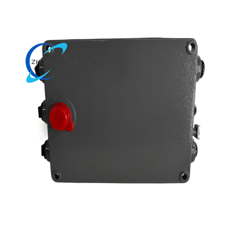
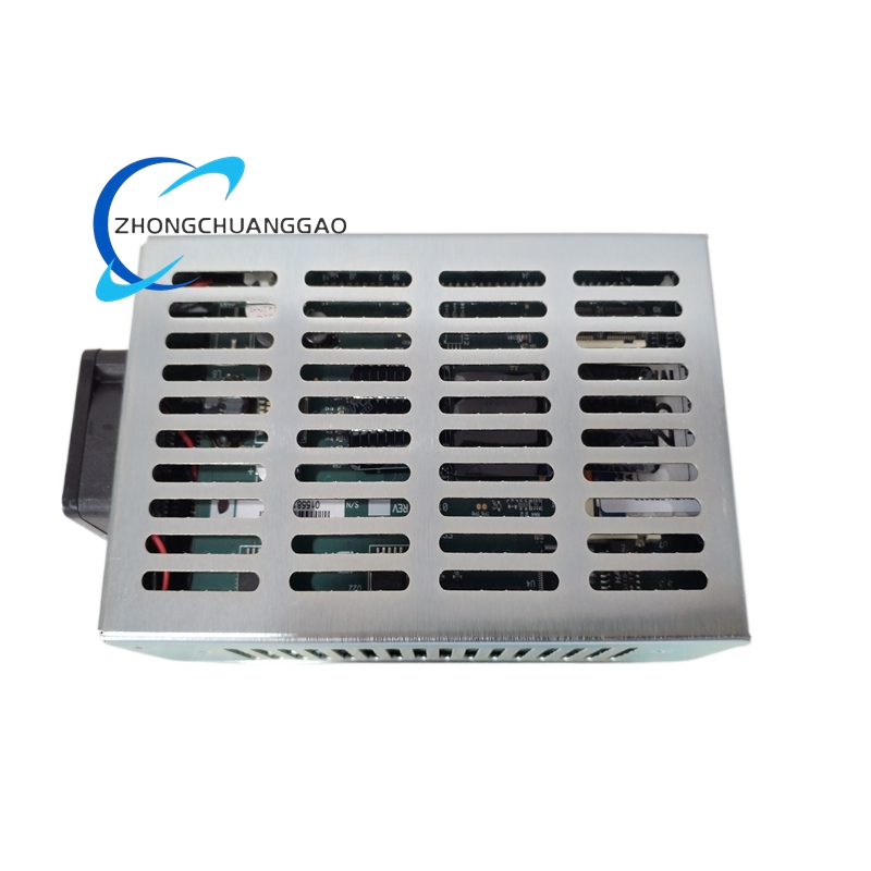
- Outer mounting casing: Cold-rolled SPCC steel plate with matte black electrostatic spray coating, sheet metal thickness 1.2mm, anti-corrosion and anti-mechanical impact characteristic, UL94-V0 fire retardant grade coating material.
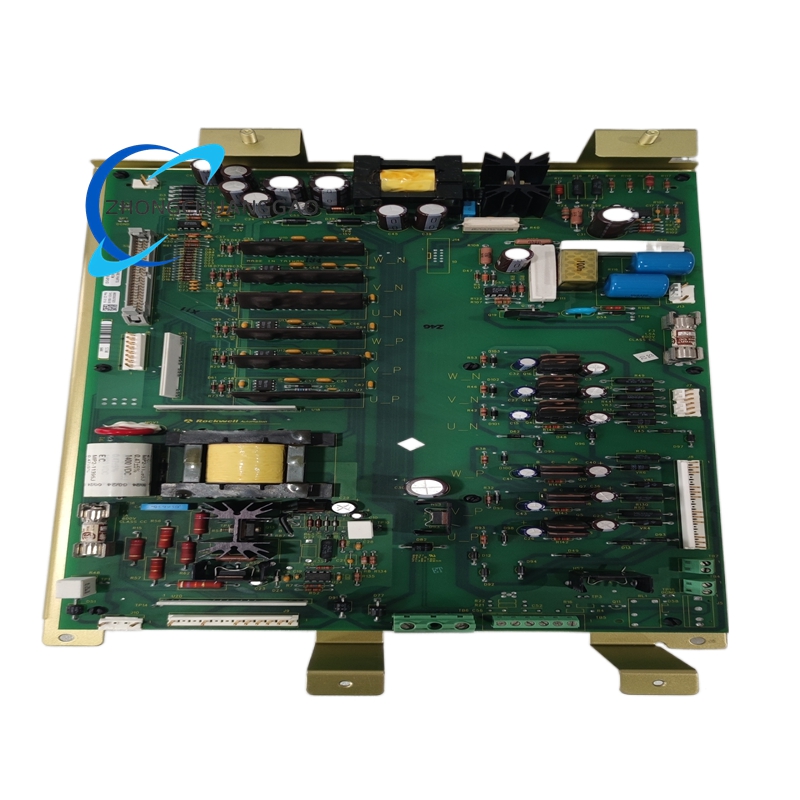
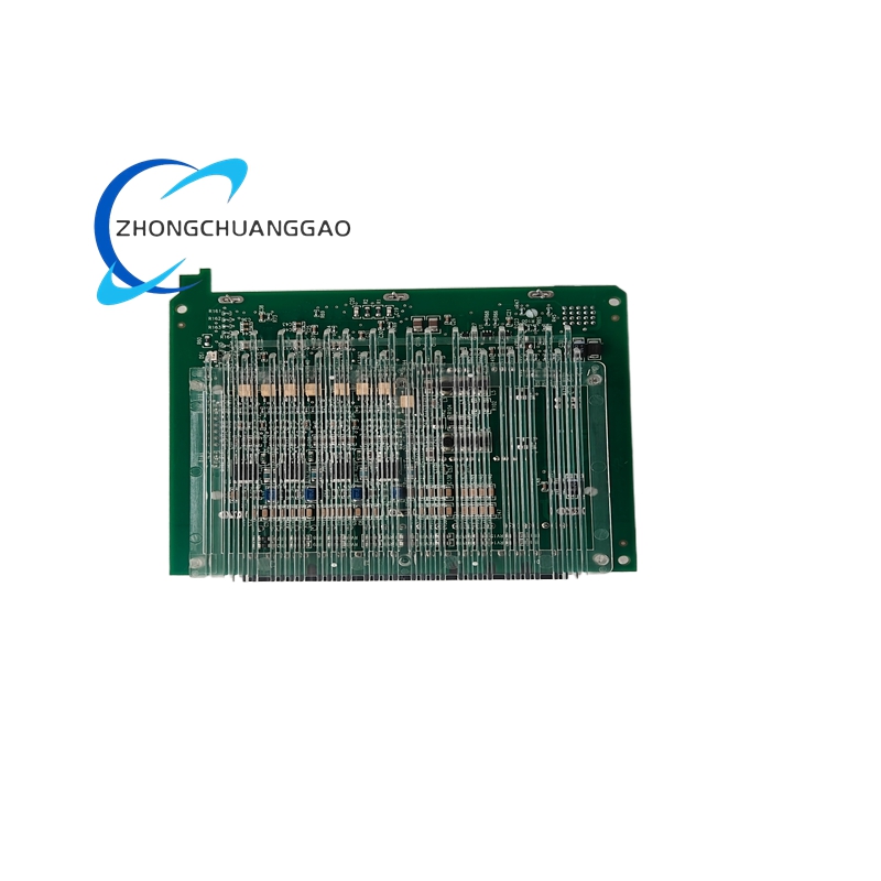
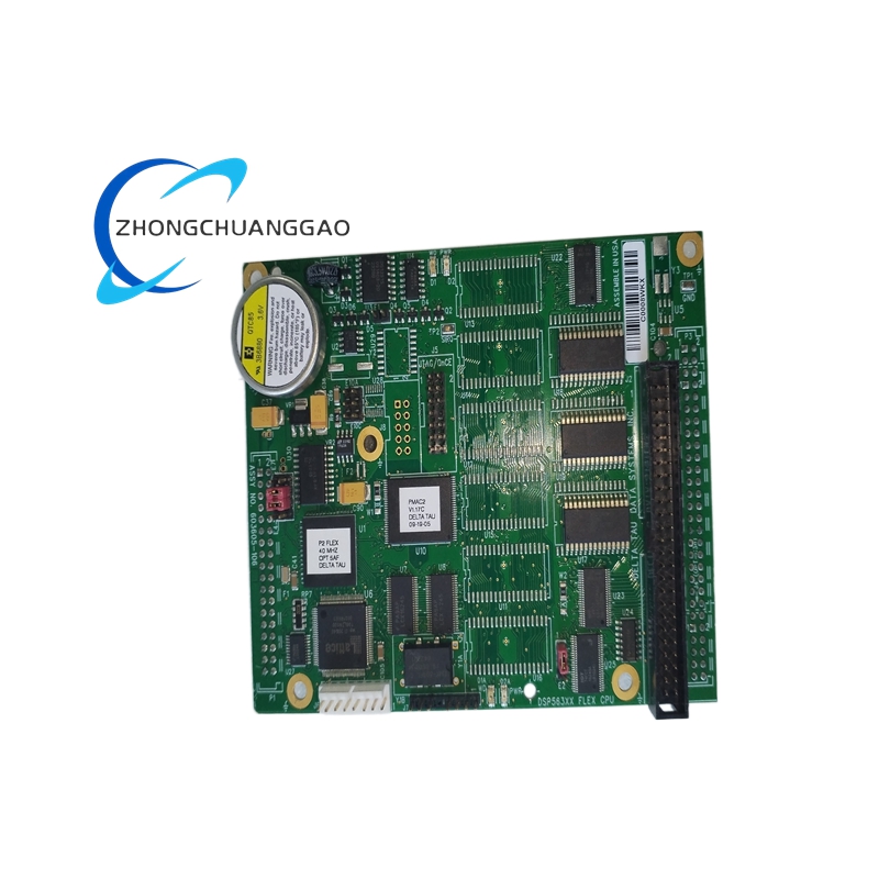
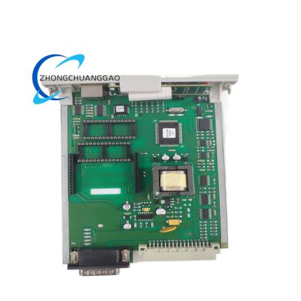
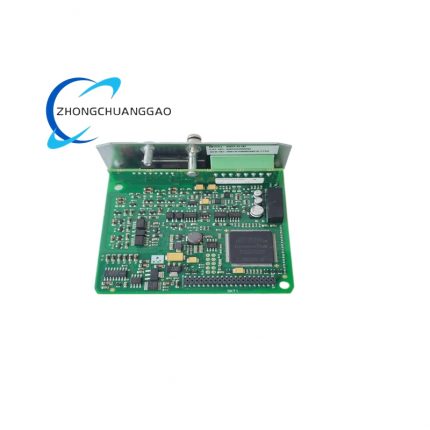
- Main control PCB substrate: FR-4 high-Tg industrial glass fiber circuit board, full board coated with acrylic three-proof insulating varnish (moisture-proof, anti-sulfidation, anti-fungal erosion).
- Core power drive components: Industrial-grade N-channel MOSFET power tube, wide-temperature range fast recovery rectifier diode, AEC-Q101 standard optocoupler for I/O channel electrical isolation.
- Passive electronic components: Metal film precision fixed resistors, high-temperature solid tantalum capacitors, high-frequency ceramic decoupling capacitors, all components rated for -40℃~+125℃ wide industrial temperature usage.
- External wiring terminal base: PA66 glass fiber reinforced nylon terminal block with silver-plated copper alloy spring shrapnel, permanent laser-etched terminal function marking characters.
- Internal backup storage accessory: Lithium primary button cell for RAM data retention, rated 3V nominal voltage with 5-year factory specified service cycle.
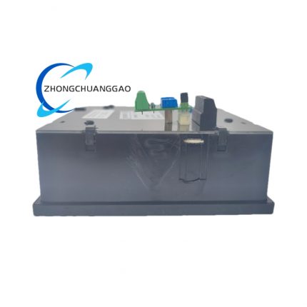
8. Structural Characteristics
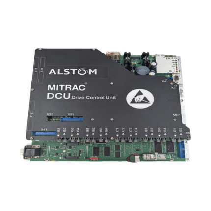
- Integral split three-layer internal layout: Front panel indicator & parameter setting layer, middle main control logic PCB layer, rear wiring terminal & power drive component layer.
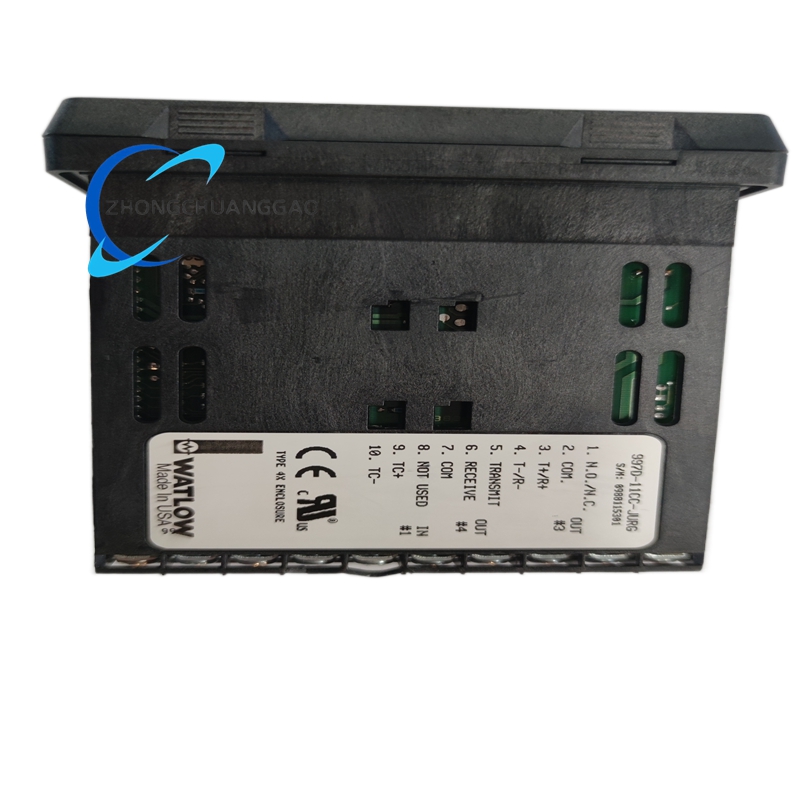
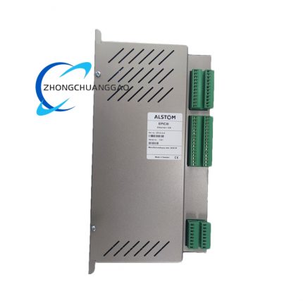
- Front panel centralized layout: Multi-status LED indicator bank, DIP current setting switch group, RS232 serial communication DB9 socket and reset physical button.
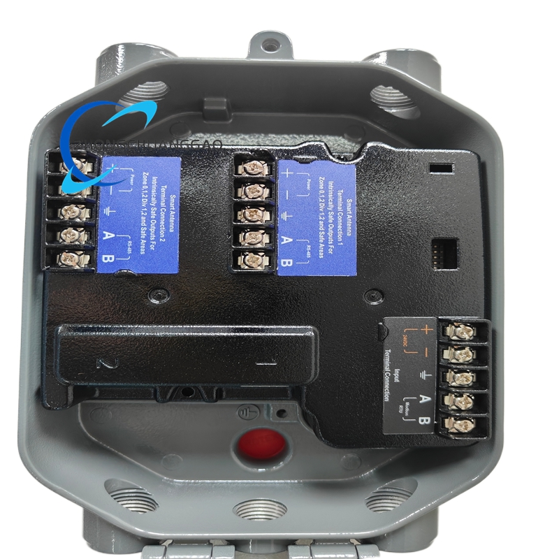
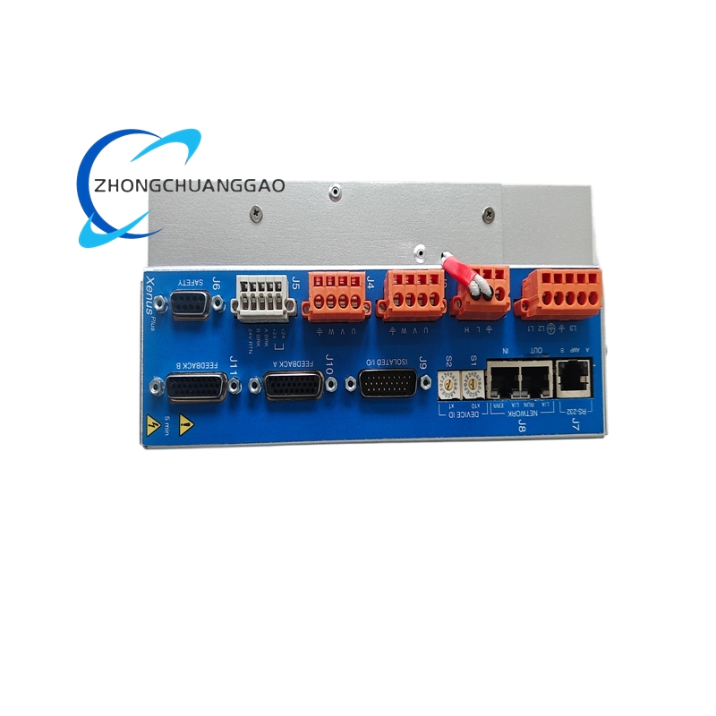
- Rear side full fixed terminal arrangement: AC power input terminal block, stepper motor four-phase winding output terminals, 16-channel digital input terminal row, 12-channel digital output terminal row and RS485 bus terminal pair, all terminals partitioned by plastic isolation ribs to avoid short-circuit risk.
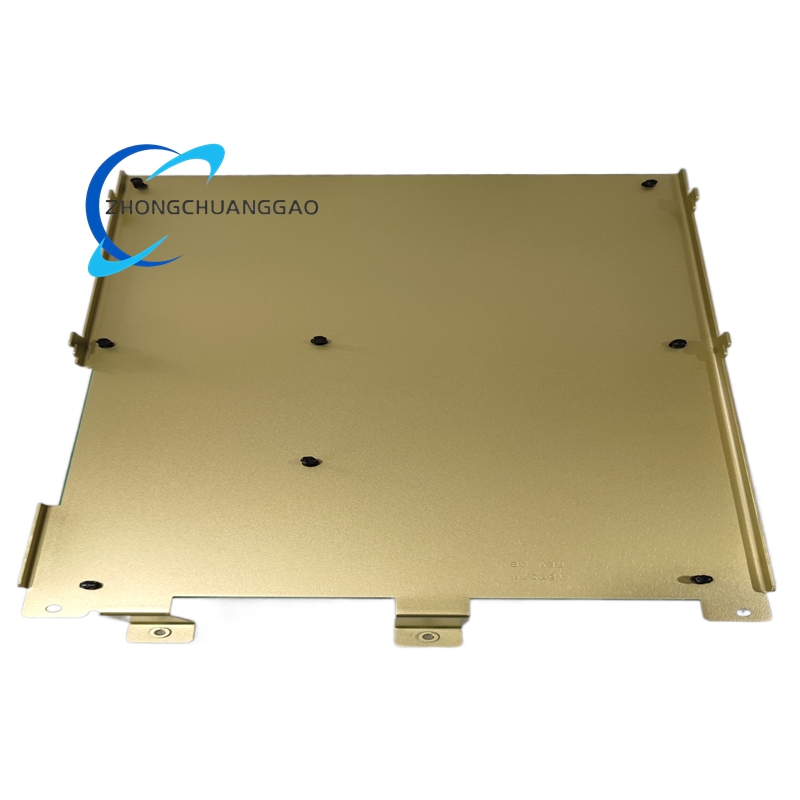
- Standard vertical DIN rail compatible fixed structure, two symmetric bending mounting lugs reserved on casing left and right sides with pre-punched fixing screw holes for screw locking inside cabinet mounting plate.
- Internal natural convection heat dissipation channel: Pre-reserved vertical air gap between power drive PCB and outer metal casing for passive heat dissipation during long-time high-load continuous operation.
- Analog drive circuit area and digital logic circuit area adopt independent separated ground routing design on PCB to suppress signal crosstalk between power loop and control signal loop.
9. Working Principle
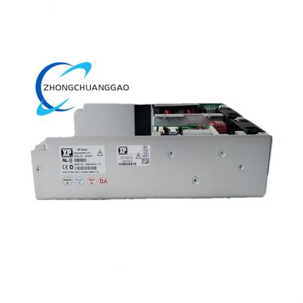
- Power Input Stage: External 120/240VAC mains power enters internal EMI filter circuit, filtered AC converts to multiple sets of isolated DC regulated power via built-in switching power supply circuit for digital control core and power drive circuit separately.
- Program Loading & Logic Operation Stage: User downloads compiled Stepper BASIC motion program from upper PC via RS232 port into internal battery-backed RAM; Core 16-bit industrial MCU reads stored program and parses motion parameters including target position, acceleration rate and operating speed.
- Signal Conversion & Microstepping Stage: MCU converts digital motion instruction into segmented PWM pulse signal, digital microstepping algorithm subdivides single basic motor step into preset fine steps and outputs modulated PWM waveform to four-phase bipolar chopper drive circuit.
- Power Drive Output Stage: High-frequency PWM signal controls on-off status of four groups of MOSFET power tubes, outputs adjustable constant RMS current to four winding terminals of matched 4-phase stepper motor to drive rotor precise stepping rotation per programmed track.
- External I/O Linkage Stage: External proximity switch, limit sensor signal is transmitted via opto-isolated digital input terminals into MCU; After internal logic judgment, MCU triggers corresponding digital output terminal to drive external auxiliary execution equipment to complete interlock action.
- Fault Diagnosis Stage: Real-time sampling circuit continuously monitors output current, internal temperature and power supply voltage; once parameter exceeds protection threshold, internal protection logic immediately cuts off motor drive output and lights corresponding fault indicator LED while storing fault code into internal register.
10. Advantage Highlights
- All-in-one integrated design eliminates separate indexer and standalone drive configuration, reduces total equipment procurement cost and cabinet internal wiring workload compared with split-type motion control scheme.
- Patented mid-speed electronic damping and idle current reduction technology effectively cuts down motor heating, mechanical vibration and noise under long-term intermittent operation condition.
- Built-in full-range hardware multi-level protection avoids permanent module damage caused by field wiring misconnection, motor winding short circuit or abnormal overload impact.
- Offline independent running function enables equipment to operate normally after removing upper configuration PC, improving production line system operation stability against upper computer failure risk.
- Universal 120/240VAC dual-input power design achieves global mains voltage compatibility without extra external step-down transformer configuration for different regional industrial power grid.
- Standard RS485 multi-drop bus networking supports centralized multi-axis synchronous control, convenient for large-scale automated production line unified program management and equipment debugging.
- Compliant with UL and CE global industrial safety certifications, satisfies safety access requirements for European and North American factory automation field installation.
11. Applicable Industries
- Packaging Machinery Industry: Automatic carton forming equipment, multi-station filling machinery, vertical and horizontal bag-making machine feeding positioning axis control.
- Precision Automation Equipment Industry: PCB board drilling routing equipment, SMT component feeding mechanism, small precision automatic indexing fixture control.
- Printing & Label Equipment Industry: Roll-to-roll flexographic printing positioning axis, automatic label die-cutting machine intermittent motion control system.
- Medical Automation Equipment Industry: Medical reagent automatic dispensing equipment, lab sample tray precision shifting and positioning drive unit.
- Textile Machinery Industry: Small-sized automatic textile jacquard equipment, yarn winding machine constant-tension stepping control module.
- Electronic Assembly Industry: Automatic connector inserting equipment, miniature component sorting machine linear motion driving control.
- Woodworking Small Automation: Desktop numerical control engraving machine micro-feed axis, small automatic cutting equipment positioning drive.
12. Installation Requirements
- Cabinet Environment Precondition: Install inside closed industrial electrical control cabinet, cabinet internal ambient temperature must stay within 0℃~+50℃, avoid installation position adjacent to heating components like power transformer or resistance heater.
- Mechanical Mounting Specification: Fix module via two side mounting lugs with M4 carbon steel screws onto cabinet metal mounting plate, keep minimum 25mm vertical air gap above and below module casing for heat dissipation air circulation.
- Power Wiring Standard: AC mains input wire adopts cross-section ≥1.0mm² copper core insulated wire; all motor winding output wiring uses shielded twisted pair cable with shielding layer single-point grounded at cabinet terminal side only.
- I/O Wiring Specification: Digital input/output control wire selects cross-section ≥0.5mm² copper wire, separate routing from high-power motor cable to avoid electromagnetic interference induction into low-voltage signal circuit.
- Communication Bus Wiring: RS485 multi-drop bus uses standardized twisted pair communication wire, install 120Ω matching terminal resistor at two extreme endpoints of total bus trunk to eliminate signal reflection distortion.
- Hazardous Area Installation Limit: Prohibit direct installation inside Zone0/Zone1 explosive hazardous cabinet; when used inside Zone2 classified cabinet, all external field wiring must pass certified explosion-proof terminal junction box access module terminals.
13. Use Precautions
- Power-on Pre-inspection Rule: Before initial power supply switching-on, verify AC input wiring matches 120VAC/240VAC terminal marking, forbid direct access of 380VAC industrial three-phase power into module AC input terminals to prevent instant internal circuit burnout.
- Parameter Setting Regulation: Complete DIP switch current configuration matching with actual stepper motor rated winding current before power-up; adjust subdivision multiple setting under equipment static power-off state only.
- Program Download Operation: Download user BASIC program under normal rated ambient temperature (22℃±3℃), avoid program writing under ultra-high/low temperature environment to prevent RAM data storage error.
- Maintenance Power Cut Rule: Cut off total AC input power supply completely before dismounting module from cabinet for maintenance; forbid live plugging/unplugging motor output wiring and communication bus terminal during powered running state.
- Spare Unit Storage Condition: Uninstalled spare modules store inside constant-temperature dry warehouse with ambient humidity below 90% non-condensing, avoid long-term storage in corrosive gas or high-temperature damp closed space.
- Firmware Upgrade Specification: Official internal firmware update only allows via Pacific Scientific dedicated 6445 configuration software, reject unknown third-party modified firmware burning which leads to original function disorder.
- Daily Surface Cleaning: Use dry anti-static lint-free cloth only to wipe front panel indicator and terminal surface dust; prohibit liquid cleaning solvent directly contacting PCB circuit and internal wiring terminals.
- Overload Operation Ban: Forbid long-term continuous operation above rated 5ARMS per-phase output current; sustained overload will cause internal power MOSFET permanent thermal ablation and drive function failure

")
")


-430x430.jpg)

Reviews
There are no reviews yet.