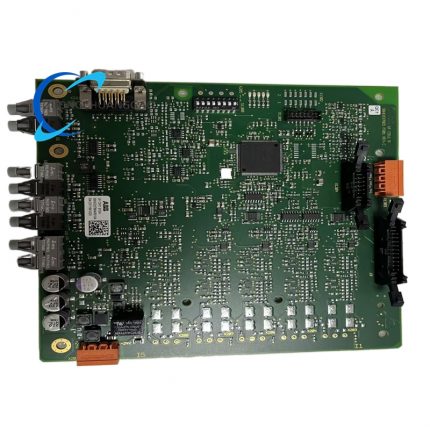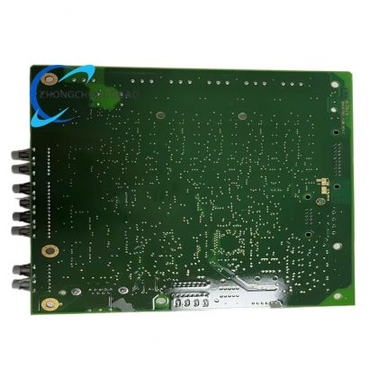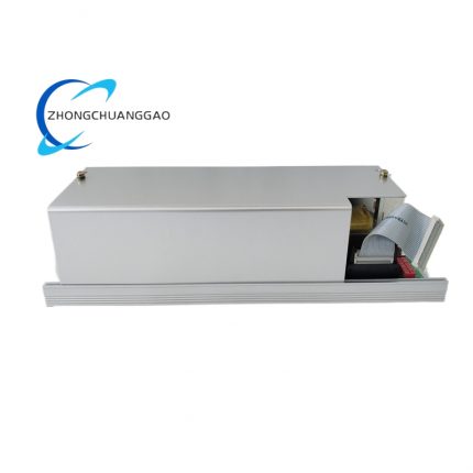
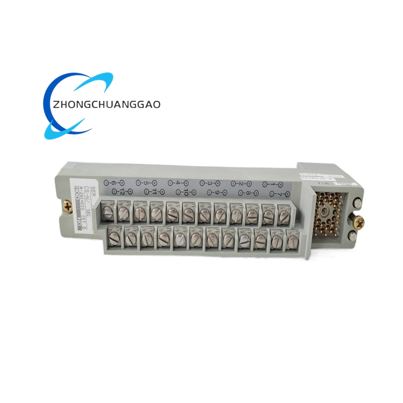
Foxboro N-2AX+DIO Ethernet Communication Module with Digital I/O
Model Series: N-2AX Series — I/A Series Network Interface Module
Manufacturer: Foxboro (Schneider Electric / Invensys)
Product Overview:
The N-2AX+DIO is a dual-port Ethernet communication module with integrated digital input/output (DIO) for the Foxboro I/A Series DCS. It provides 10/100 Mbps Ethernet connectivity for system integration, HMI access, and remote engineering, while also offering 8 digital inputs and 8 digital outputs for local discrete I/O control.
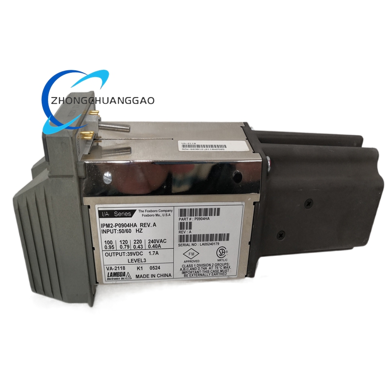
Foxboro IPM2-P0904HA Intelligent Valve Positioner
Model Series: IPM2 Series — Smart Positioner
Manufacturer: Foxboro (Schneider Electric / Invensys)
Product Overview:
The IPM2-P0904HA is a HART-compatible intelligent electro-pneumatic valve positioner from the Foxboro IPM2 product family. It provides precise control of pneumatic control valves by converting a 4–20 mA control signal into a proportional pneumatic output pressure. It supports HART 5/7 protocol for digital communication and advanced diagnostics.
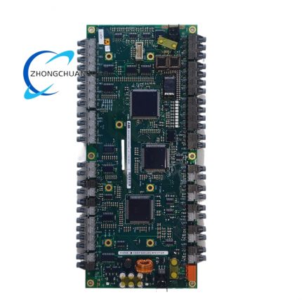
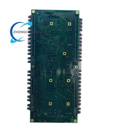
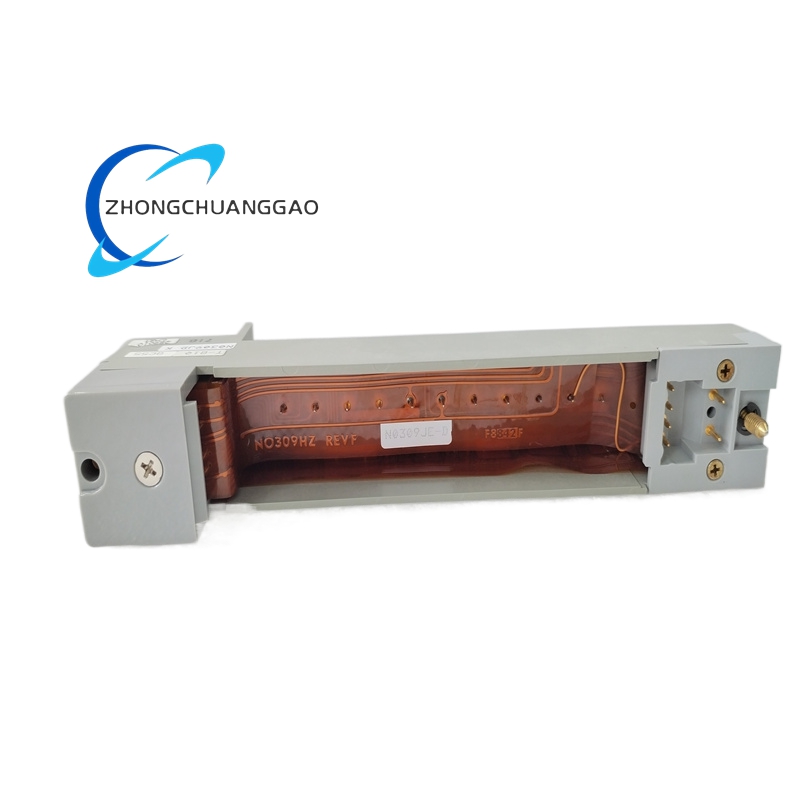
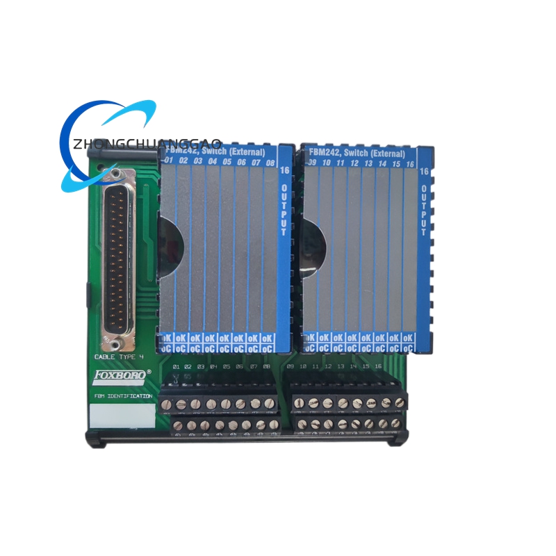
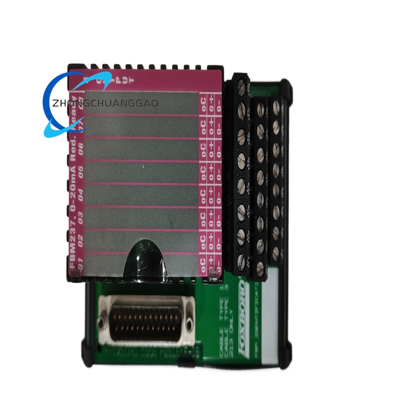
Foxboro FBM242 RH916YY High-Speed Counter
Product Classification: High-Speed Event Counter and Pulse Input Module
Product Introduction:
The Foxboro FBM242 with part number RH916YY is a high-speed counter and pulse input module designed for precise measurement of frequency, totalization, and event counting in the Foxboro I/A Series DCS. It accepts high-frequency pulse signals from flow meters, turbine meters, encoders, and other pulse-generating devices. The RH916YY revision identifies the specific hardware configuration of this module.
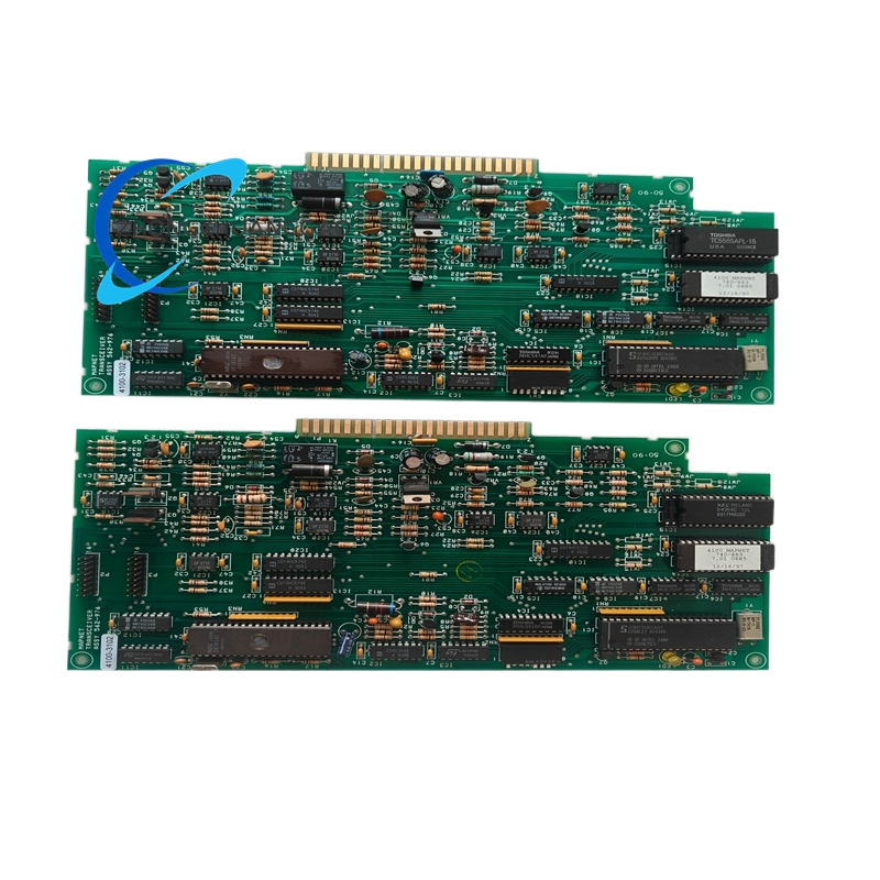
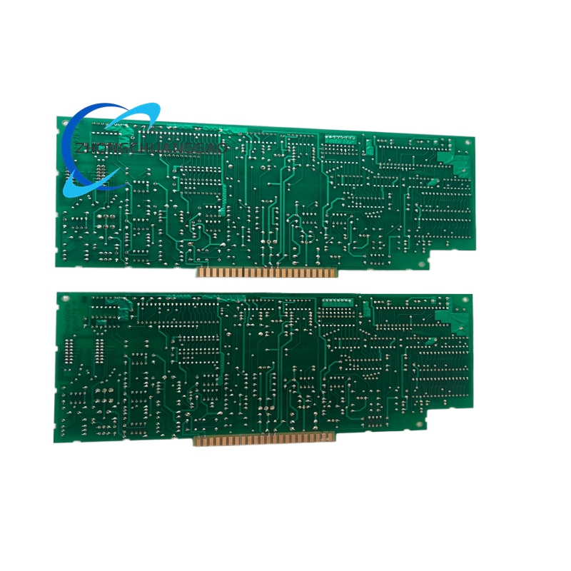
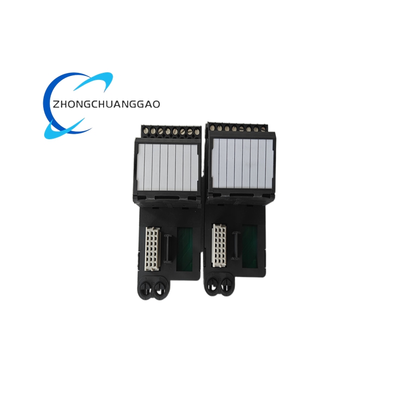
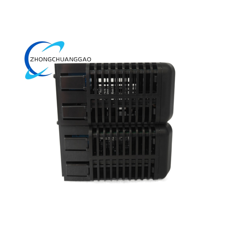
Simplex 4100-3102
Product Brief Introduction
The Simplex 4100-3102 is a dedicated field-mounted auxiliary I/O accessory module engineered exclusively to match the Simplex 4100 series intelligent addressable fire alarm control system. It serves as the intermediate signal conversion and relay switching unit between the main fire alarm controller, field fire detection devices, auxiliary building facility equipment and peripheral notification appliances. The module realizes digital bus signal parsing from the main control unit and converts parsed commands into dry contact switching signals or passive input acquisition signals for external equipment linkage control and status feedback collection.
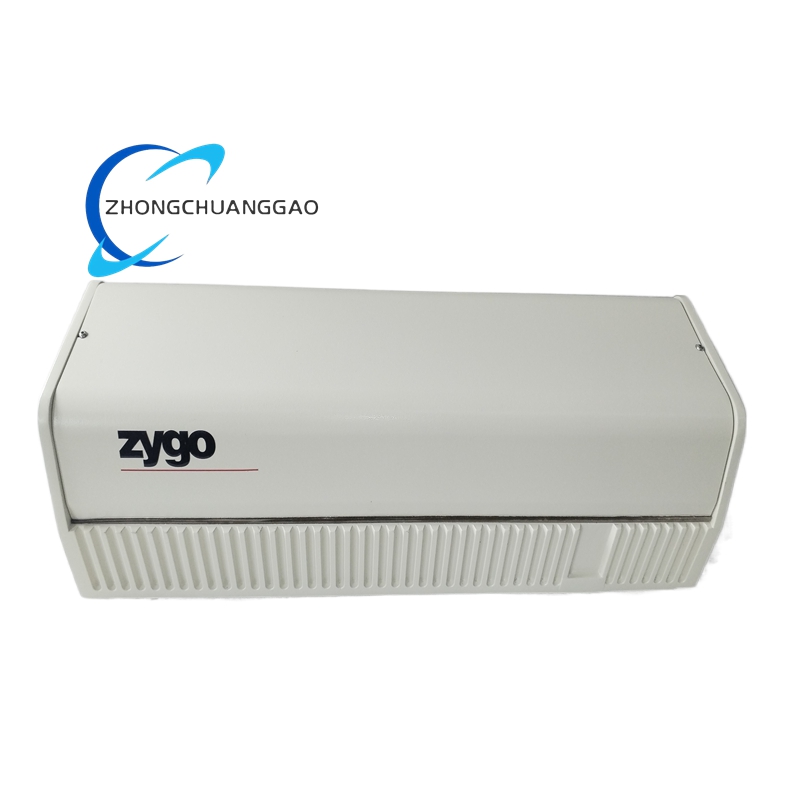
Zygo 7702
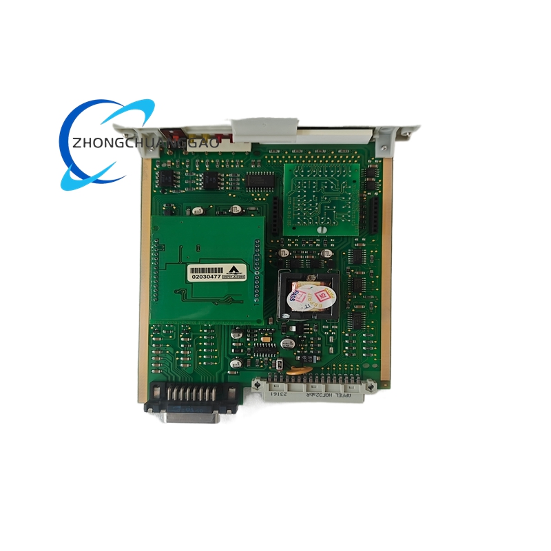
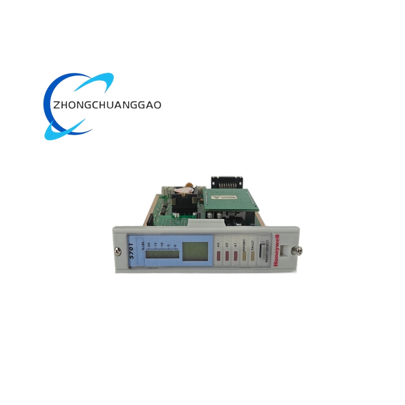
Honeywell 05701-A-0302
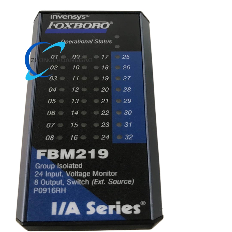
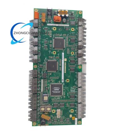
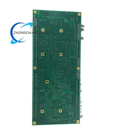
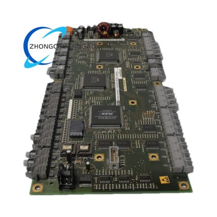
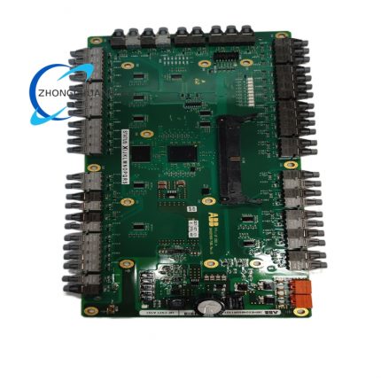
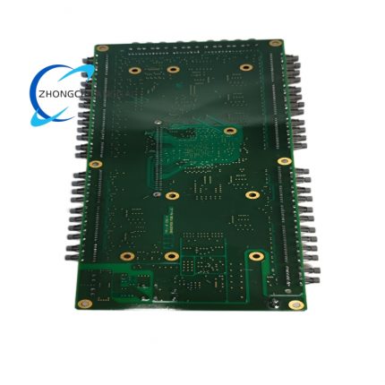
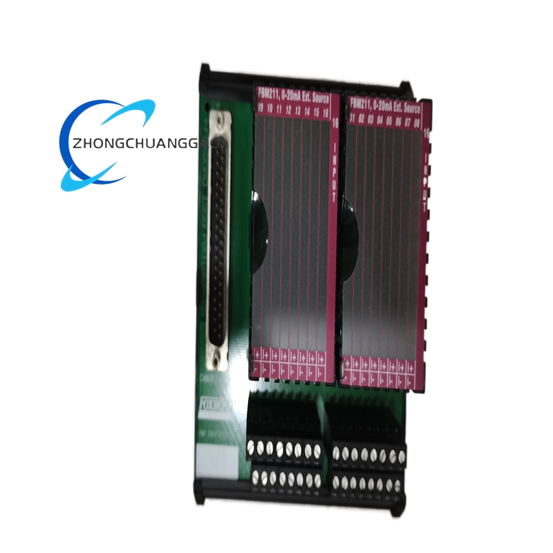
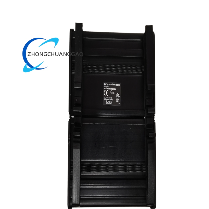
Foxboro FBM219 Control Processor Module
Product Classification: 32-Bit RISC Control Processor
Product Introduction:
The Foxboro FBM219 is the primary control processor module serving as the central computing engine within the Foxboro I/A Series Distributed Control System (DCS). It executes all control strategies, sequential logic, arithmetic computations, and data management tasks for the entire control system. This module is the brain of the I/A Series architecture and interfaces directly with all I/O modules, communication modules, and operator stations.
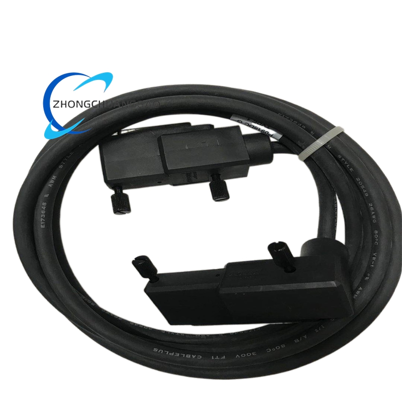
Foxboro P0916JY Pneumatic Valve Positioner
Product Type: Special Configuration Pneumatic Valve Positioner
Product Introduction:
The Foxboro P0916JY is a special configuration variant of the P0916 series pneumatic valve positioner. The JY suffix denotes a custom or application-specific configuration typically requested for OEM integration, special signal requirements, or unique mounting arrangements. This model is configured per customer specification and may include modified input ranges, special output signals, custom mounting, or proprietary feedback linkages.
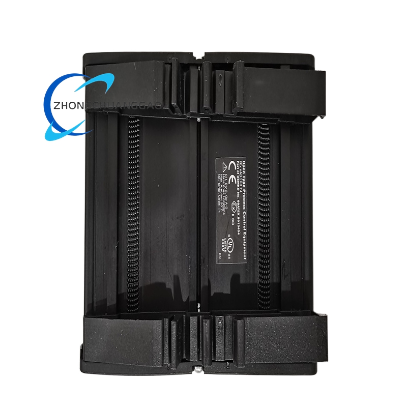
Foxboro P0916JTOE Pneumatic Valve Positioner with Junction Box Totally Enclosed
Product Type: Junction Box Totally Enclosed (JTOE) Pneumatic Valve Positioner
Product Introduction:
The Foxboro P0916JTOE is a pneumatic valve positioner equipped with an integral totally enclosed junction box (JTOE) for electrical connection termination. The JTOE suffix indicates the positioner includes a sealed, gasketed junction box that provides NEMA 4X / IP66 rated termination point for all electrical wiring. This configuration is used when field wiring must be terminated at the positioner rather than at a remote junction box, providing a single-point connection that is fully weatherproof.
Foxboro P0916FH Field-Hardened Pneumatic Valve Positioner
Product Type: Field-Hardened (FH) Pneumatic Valve Positioner
Product Introduction:
The Foxboro P0916FH is a field-hardened variant of the P0916 series pneumatic valve positioner designed for extreme environmental conditions including extreme temperatures, high vibration, heavy dust, and washdown exposure. The FH suffix indicates the unit has undergone enhanced environmental hardening beyond standard specifications. It maintains full 4-20 mA to 3-15 psi performance in the harshest field conditions.
Foxboro P0916DC Pneumatic Valve Positioner
Product Type: Double-Acting Cylinder Pneumatic Valve Positioner
Product Introduction:
The Foxboro P0916DC is a double-acting cylinder configuration pneumatic valve positioner. The DC suffix specifically denotes the double-acting (DA) actuator interface with a 6-30 psi (0.4-2.0 bar) output signal range option. This model is designed for double-acting pneumatic actuators that require air pressure on both the open and close strokes, providing higher thrust and faster stroke times than single-acting designs.
Foxboro P0916CC Pneumatic Valve Positioner
Product Type: Compact Pneumatic Valve Positioner
Product Introduction:
The Foxboro P0916CC is a compact configuration variant of the P0916 series pneumatic valve positioner. The CC suffix denotes a reduced-size housing designed for applications where space is limited on the valve actuator. It delivers full 4-20 mA to 3-15 psi conversion in a smaller footprint while maintaining the same performance specifications as standard models.